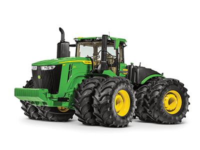
Precision farming has begun to be a very important tool in today’s farming applications where the input costs are very high precision equipment from John Deere will minimize the input costs drastically…
AFGRI Equipment has highly equipped workshops in South Africa, Zambia, Zimbabwe, Botswana, Ghana and Western Australia. Maintenance and repairs are done on all John Deere products and other products that AFGRI Equipment delivers. We have Specialists supporting the workshop personnel with repairs and diagnostics on products.
Having the utility vehicles come pre-wired for a winch from the factory greatly reduces the winch install time. Two of the RSX860i chassis come from the factory pre-wired for a winch: all power steering models and the winch-ready chassis.
Components included in the winch-ready chassis factory installed:
Winch wiring harness
Negative winch battery cable
Winch disconnect wiring harness
Chassis with prewiring for winch
A dealer installed version of the WARN® ProVantage 3500-lb (1587.6-kg) winch for these chassis is available through Parts. Please reference the Price Pages/Configurator for the attachment number.
The following factory-installed packages are available as PR15 (priority replenishment) configurations, and are targeted to be available at your dealerships within 15 calendar days of order entry.
RSX860i Power Steering with WARN® winch and protection package (available in green and yellow, REALTREE® HARDWOODS HD® camo).
Shown in camo; also available in green and yellow. Shown with optional spot lights and half windshield.
Factory package includes:
Power steering
Yellow alloys on green and yellow vehicles, black alloys on camo vehicle
Sport seats
FOX® monotube shocks
2-in. (50.8-mm) front receiver with recovery loops
WARN® 3500 ProVantage winch
Pre-runner bumper
Rear bumper
Cargo box rails
RSX860i power steering winch ready with FOX 2.0 Performance Series piggyback shocks and protection package (available in green and yellow)
Shown with optional spot lights, half windshield, winch
Factory package includes:
Power steering
Winch ready
14-in. (355.6-mm) yellow alloys
Sport seats with sport steering wheel
FOX 2.0 Performance Series shocks with piggyback reservoir
Pre-runner bumper
Rear bumper
Cargo box rails
Build-to-order options available
The RSX860i can be configured the way the operator wants it. The build-to-order vehicles start with a choice of three different chassis:
Base chassis: no power steering, not winch ready. The vehicle can still be configured with the choice of colors, wheel/tires, seats, shocks and protection components.
Winch-ready chassis: no power steering, winch ready from the factory. Configurable with choice of colors, wheel/tires, seats, shocks, winch and protection components.
Power steering chassis: power steering, winch ready. Configurable with choice of colors, wheel/tires, seats, shocks, winch and protection components.
If orders are build to order, they will be sourced and a FDD assigned based on availability.
REALTREE HARDWOODS HD is a trademark of Jordan Outdoor Enterprises Limited. Warn is a trademark of Warn Industries, Inc. Fox Shocks is a trademark of Fox Factory Incorporated.
The cargo box consists of a high-density polyethylene copolymer composite material that eliminates rust, dents, and reduces noise. This large, one-piece design has rounded inside corners to ensure material removal when tilted. The composite box is highly ribbed and supported with a welded steel-ladder structure to ensure hard-driving performance and longevity. The three highly styled exterior pieces are made of thermoplastic polyolefin (TPO) for extra durability.
Cargo box tailgate
Tailgate handle
Removable tailgate
Tailgate pivot
Removable lanyards
The tailgate can be opened or removed for easier cleanout and to carry longer items. It features truck-like performance and can be operated with one hand.
The tailgate’s pivot point is made of hardened steel for durability and designed for tool-less removal. The standard lanyards can also be disconnected without tools to remove the tailgate for convenient loading and unloading tasks.
Cargo box tilt and removal
Integrated handle for manual cargo-box tilt
The cargo box ease of use is critical to performing tasks quickly and efficiently. Starting with the truck-style tailgate, the removal of content in this cargo box is much easier. The manual release functions as the lift lever as well, done in a smooth, one step motion. It can even be tilted from both sides of the vehicle. To reduce the overall effort of lift, the pivot point of the cargo box is closer to the center. The combination of easy-to-use attributes makes this cargo box best in class.
With the removal of two bolts, the cargo box can easily be detached from the vehicle frame for ease of servicing.
Integrated tie-down points
Integrated tie-down point in cargo box bed
Additional tie-down points
The cargo box offers integrated tie-down points for increased versatility. Tie-down points are located in the following areas:
Flip-up D-shaped rings in all four corners inside the cargo-box bed
Multiple points along the edge of the cargo box side walls
Tie-down bars on either side of the cargo box with optional cargo box rail kit. This kit also provides a mounting system using accessories that possess the 25.4-mm (1-in.) quick clamp.
Optional accessories
Cargo box rail system
Optional accessories for the cargo box include:
Factory-installed cargo box rail system
Cargo box bed mat
Cargo box wall extensions
Specifications
Length
32.3 in. (82 cm)
Width
47.6 in. (120.9 cm)
Depth
11.7 in. (29.6 cm)
Volume
8.9 cu ft (0.25 m³)
Weight capacity
400 lb (181.4 kg)
Dump angle Bed height (from ground)
45 degrees 30 in. (76.3 cm)
CAUTION: Carrying extra-long cargo that extends beyond the box can adversely affect stability.
The Gator™ RSX High-Performance Series Utility Vehicles are equipped with rack and pinion steering with optional power steering, and a dual A-arm front suspension. These automotive-type systems exhibit excellent handling characteristics, as well as responsive steering and low steering effort.
Automotive-type rack and pinion steering with optional power steering
RSX860i with optional power steering
Automotive-type rack and pinion steering features include:
Optional electronic power-steering assist system (EPAS). Features of EPAS include:
Anti-kickback feature reduces the amount of steering unwinding when traversing difficult terrain.
The system is speed sensing and adjusts steering effort as the speed of the vehicle changes.
As speed increases there is less steering assist for improved road feel.
As speed decreases steering assist increases to give lower steering efforts for improved maneuverability.
A warning/functional light on the instrument panel provides self-diagnostics and a warning light in the situation of no assist.
Torque sensor measures steering wheel input so the on-board computer can provide the appropriate output for various driving situations.
Steel ball-bearings secure the steering shaft and delivers smooth, responsive operation
Tight turn radius of 12.3 ft (3.7 m) for excellent maneuverability
Completely sealed rack-and-pinion for long life
Low steering ratio (lock-to-lock steering wheel rotations) provides more responsive steering and less operator input
Shaft U-joints are phased for a smooth, uninterrupted motion of the steering wheel
Ackerman steering design provides more responsive steering, decreases tire wear when used on hard surfaces and is turf friendly (see description below)
Minimal bump steer eliminates unintended vehicle direction changes when traversing terrain and permits less feedback to the steering wheel (see description below)
The tire scrubbing, which also creates unwanted heat and wear in the tire, can be eliminated by turning the inside wheel at a greater angle than the outside one (Ackerman steering).
NOTE: Some competitors use parallel steering instead of Ackerman steering.
Bump steering defines the change in the forward steering angle (thus wheel position) as the suspension travels through its full motion. A large amount of angular change (5 degrees to 7 degrees) will alter the vehicle’s direction and excessively move the steering wheel.
RSX front suspension detail
To complement the capable powertrain on the RSX860i, the RSX is equipped with four-wheel independent suspension. This unique suspension setup provides an unparalleled ride over challenging terrain and excellent handling through corners.
The engineering team in collaboration with engineering firms that consult with Formula 1®, NASCAR®, and INDYCAR® teams, built a sport-tuned suspension system for class-leading operator comfort, no matter what the terrain, and handling that makes one think they are on rails.
Dual A-arm front suspension features include:
Dual, wide-arch A-arm design provides maximum front-wheel control, precise steering, and maximum ground clearance out to the wheel
9 in. (23 cm) of travel provides ample compression and wheel extension, which keep all four wheels on the ground for superior traction and vehicle control
Exclusive aluminum-body, high-pressure monotube shocks or piggyback shocks; both provided by Fox Shocks™ racing shocks (see more details below)
Solid anti-roll bar, with fully rubber isolated connecting links and pivots, is tuned to provide the most agile and predictable handling
Camber during compression to compensate for body roll and to maintain an optimal tire contact patch for improved cornering grip
Increasing vehicle width during compression for additional stability.
High-strength ASTM 80-55-06 ductile cast-iron knuckle and upper A-arm to support the high stresses of the shocks, constant velocity (CV) shaft, and wheels
Automotive-style fully boxed and welded-steel lower A-arms to minimize unsprung mass and maximize strength
Maintenance-free rubber torsional A-arm pivots for long life and quiet operation
CV shaft protection from sticks that may puncture the rubber boot
Anti-dive front suspension geometry provides a solid platform for confident braking
RSX rear suspension detail
Multi-link independent rear suspension (IRS)
Multi-link IRS rear suspension features include:
Exclusive multi-link semi-trailing arm rear suspension moves wheel rearward and outward in compression
9 in. (23 cm) of travel provides ample compression and wheel extension, which keeps all four wheels on the ground for superior traction and vehicle control
Exclusive aluminum-body, high-pressure monotube shocks or piggyback shocks; both provided by Fox Shocks (see more details below)
Solid anti-roll bar, with fully rubber isolated connecting links and pivots, is tuned to provide the most agile and predictable handling
Camber during compression to compensate for body roll and to maintain an optimal tire contact patch for improved cornering grip
Increasing vehicle width during compression for additional stability.
High-strength ASTM 80-55-06 ductile cast-iron knuckle and lower A-arm to support the high stresses of the shocks, CV shaft, and wheels with the toughness to survive impacts from boulders
Heat-treated aluminum cast upper A-arms to minimize unsprung mass
Maintenance-free rubber torsional A-arm pivots for long life and quiet operation
Standard Fox Shocks
Standard Fox Shocks
Standard equipment shocks on the base model– front and rear suspension
Exclusive aluminum-body, high-pressure monotube Fox racing shocks
Fully adjustable spring preload for different driving styles
High-pressure nitrogen gas is separated from the damping oil by an internal floating piston (IFP). The separation prevents aeration (frothing) and viscosity degradation of the oil which improves damping consistency and performance fade.
Pressure and heat generation in the monotube is less than a traditional twin-tube shock, allowing for better vehicle control in aggressive conditions.
The single aluminum shell of the monotube design allows for more efficient heat rejection and lower overall unsprung mass.
Mounting the shaft end of the shock to the suspension arm lowers the unsprung mass of the suspension system, leading to improved suspension response.
Upgrade Fox 2.0 Performance Series shocks
Reservoir with compression adjustment
Upgrade Fox 2.0 Performance Series shocks
Upgrade shocks—Front and rear suspension
RSX tuned Fox 2.0 Performance Series shocks
Fully adjustable spring preload for different driving styles and ride height settings
Piggyback reservoir houses high-pressure nitrogen gas, separated from the damping oil by an internal floating piston (IFP). The separation prevents aeration (frothing) and viscosity degradation of the oil which improves damping consistency and performance fade.
Large, 2.0 aluminum bodies help reduce internal pressures and improve heat dissipation, which results in consistent fade-free performance in aggressive riding conditions.
Compression adjustment allows the user to tune damping rates for different riding preferences and trail conditions
Tuned with Fox factory support on some of the most grueling trails in the United States
Fox Shocks is a trademark of Fox Factory Incorporated. NASCAR is a trademark of NASCAR. INDYCAR is a trademark of Brickyard Trademarks Incorporated. Formula 1 is a trademark of Formula One Licensing BV, a Formula One Group Company.
Choose your dealer to contact via the drop down list.
Choose a dealership to contact:
ActiveSeat and controls
John Deere’s ActiveSeat utilizes electrohydraulic technology in combination with air suspension, providing the operator with enhanced ride quality over standard air-suspension seats.
Operator movements are monitored in order to reduce vertical movement. An ActiveSeat suspension can isolate the operator from up to 90 percent of vertical movements typically seen in tractor applications.
The system uses a hydraulic cylinder that is connected to a control valve assembly. Electrohydraulic valves located in the control valve assembly automatically react to inputs from two sensors, a position sensor and an accelerometer. Inputs from these two sensors control oil flow from the tractor to the hydraulic cylinder to reduce the vertical movement of the operator.
ActiveSeat left armrest
The John Deere ActiveSeat has many of the same features of the ComfortCommand™ seat with the addition of a ride firmness switch. The ride firmness switch is located on the left-hand armrest and replaces the suspension shock-dampening seat attenuation lever on the front right-hand side of the ComfortCommand seat controls.
The ride firmness switch has three positions: plus, minus, and mid position. The three positions provide three different levels of seat performance:
The plus position provides the greatest degree of ride firmness. This position allows more of the tractor’s inputs to be felt by the operator (slightly rougher ride).
The minus position provides the least degree of ride firmness, allowing minimal tractor inputs to reach the operator, resulting in maximum seat performance.
The mid position allows a balance between the plus (+) and minus (-) settings.
The ActiveSeat is also available as a heated leather seat for increased comfort and easier cleaning. For tractor applications where operating speed is not limited by the implement, the ActiveSeat can allow for faster field speeds and increased overall comfort and productivity.
NOTE: The John Deere ActiveSeat is not available on track tractors.
Option code
Description
2061
Premium CommandView III Cab with Active Seat
All 8R and 8RT Series Tractors come standard with an 85-cc displacement integrated hydraulic pump. This pump provides 227.1 L/min (60 gpm) of hydraulic flow.
A dual-pump option, featuring 85-cc and 35-cc displacement hydraulic pumps, is available for all 8R wheel models. The dual-pump system provides a hydraulic flow of 321 L/min (85 gpm), ideal for running at lower engine speeds.
Operating the tractor at reduced engine rpm contributes to a quieter cab, reduced fuel usage, and maintains the vacuum while turning and raising the planter on end rows. At 1500 erpm with a 321 L/min (85 gpm) system there will be an available flow of 229 L/min (61 gpm). This is an improvement over an available 162 L/min (43-gpm) flow when operating with a 227 L/min (60 gpm) system at 1500 erpm.
The maximum flow through one selective control valve (SCV) with a standard coupler is 132 L/min (35 gpm). A 19.1-mm (3/4-in.) high-flow coupler allows for a maximum flow rate out of one SCV of 153 L/min (40.5 gpm).
The hydraulic system is a closed-center, power-on-demand system using a load-sensing pressure-flow compensated axial piston pump with full-flow charge and flow prioritization for steering and brakes.
The pump outlet pressure available on demand can range from 3000 kPa (435 psi) for track models and 4000 kPa (580 psi) for wheel models at low standby to 20,400 kPa (2958 psi) at high standby.
Hydraulic pump options:
85-cc displacement, 227-L/min (60-gpm) hydraulic pump
NOTE: Standard on all 8R models.
85-cc and 35-cc dual pump option, 321-L/min (85-gpm)
7R e23 transmission
The e23 transmission delivers smooth shifting and intuitive controls with Efficiency Manager™ feature in a reliable 23-speed PowerShift™ transmission. The e23 transmission is available for all 7R, 8R, and 8RT Series Tractors.
The e23 has evolved from more than 50 years of John Deere PowerShift technology. With more automatic features, the e23 is easy to operate for all levels of operator experience. For more advanced operators looking to customize the transmission to best fit their operation, the e23 offers a custom mode.
As the next generation of PowerShift technology, e23 delivers the strength to handle sudden, high-torque power loads while maintaining responsive, quick, and smooth shifts. The e23 with Efficiency Manager provides improved fluid efficiency and overall productivity with limited input from the operator.
e23 options
e23 transmission 42 km/h (26 mph) with Efficiency Manager
e23 transmission 50 km/h (31 mph) with Efficiency Manager
Even gear spacing for optimal performance
The e23 has 23 forward gears and 11 reverse gears, which are all evenly spaced. Forward gears are spaced 15 percent apart, while reverse gears are spaced approximately 30 percent apart, providing operators smooth shifting between gears. Even spacing improves efficiency and allows for smooth, automated shifts when using Efficiency Manager. The e23 can reach maximum forward ground speed in gear F20. As a result, gears F21-F23 maintain maximum ground speed at reduced engine rpms to save fuel.
e23 controls
The e23 is available with either a right-hand or left-hand reverser.
Right-hand reverser
Right-hand reverser
A convenient, right-hand reverser is available with the e23 transmission. The reverser is located on the CommandARM™ as shown above.
Forward direction selector
Reverse direction selector
Neutral position
Electronic park lock
Right-hand reverser equipped models use three main controls to operate the tractor:
Foot brake with integrated AutoClutch
Set speed adjuster
Gear selector control lever with integrated reverser
The right-hand reverser control strategy combines speed control and direction control into one multi-function lever that is conveniently located on the CommandARM. This is a good choice for most common field applications since tractor speed and direction are not constantly being adjusted by the operator.
Left-hand reverser
Left-hand reverser
Left-hand transmission lever
An easy-to-use left-hand reverser is available with the e23 transmission and includes the same functions as the right-hand reverser. The reverser control is located at the 10 o’clock position on the steering column for intuitive control.
The five-position, left-hand reverser column incorporates the following controls:
Forward direction selector
Reverse direction selector
Neutral position
Electronic park lock
Left-hand reverser equipped models use four main controls to operate the tractor:
Foot brake with integrated AutoClutch™ function
Set speed adjuster
Gear selector control
Multi-function left-hand reverser
The left-hand reverser control strategy separates the direction control lever from the speed/gear control lever on the CommandARM. This strategy is a good choice for operations requiring the right hand to run multiple operations on the CommandARM or applications requiring constant directional changes like loader work.
Determining which reverser is best suited for a specific operator depends on a few key factors. Consider the following to help choose between a left- or right-hand reverser.
Operator preference and ergonomic benefits.
Operators in loader applications might prefer a left-hand reverser since direction changes occur frequently while their hands are on the steering wheel (near the left-hand reverser location).
Producers primarily in row-crop applications using features like AutoTrac™ assisted steering system or operating with the seat swiveled to the right for easy access to monitors and displays might find the right-hand reverser more convenient. Speed and directional controls are in one location on the CommandARM.
Foot brake with integrated AutoClutch function
The electrohydraulically controlled brakes on e23-equipped tractors have an integrated AutoClutch function.
At low idle only, the tractor will stop by depressing only one brake pedal.
Pressing both brakes (locked together) simultaneously will stop the tractor from any ground or engine speed.
Braking can be done on flat ground or steep slopes simply by using the brake pedals; it is not necessary to depress the clutch.
It is recommended to lock the brake pedals together when operating on roads.
Foot brake with integrated AutoClutch
AutoClutch sensitivity can be adjusted through the Generation 4 CommandCenter™ display. AutoClutch can be deactivated on e23 transmissions as well; however, it will be reactivated after every key start.
Full auto mode
Full auto main page
Full AUTO mode enables the tractor to make adjustments to the transmission operating mode automatically, based on engine and transmission speed and the load on the tractor. This means the tractor will shift up and throttle back automatically to reach the desired ground speed efficiently. Operators have the ability to set the maximum forward and reverse speeds for the tractor in their particular application.
When shifting in full AUTO mode, the transmission shifts set speeds, meaning the transmission may not necessarily shift gears each time the lever is bumped. Efficiency Manager is automatically engaged while operating in full AUTO mode. As a result, shifting will not take the tractor out of Efficiency Manager in full AUTO mode.
Stopping the tractor using AutoClutch
During transport, it may be desirable to use the AutoClutch feature to stop the tractor when approaching an intersection or turn. Braking the tractor using the AutoClutch at high ground speed and engine speed will require high brake-pedal force.
Rather than using AutoClutch alone, reduce the engine rpm and reduce the e23 to a slower commanded speed before applying the AutoClutch. This will help to reduce the force needed to stop the tractor with the AutoClutch. The tractor will accelerate to the previously commanded speed upon release of the AutoClutch, repositioning of the hand throttle and increasing the commanded speed.
NOTE: The preferred method of stopping heavy towed loads is to reduce the e23 commanded speed and lower engine rpm first, and then depress both brake pedals. (Brake pedals should be locked together.)
Using individual brake pedals – implement hook-up
Individual brake pedals can be used to assist slow-speed off-road turning, such as hooking up to an implement. At low idle, the AutoClutch feature will stop the tractor if the operator depresses only one brake pedal.
To assist in hooking up an implement, depress either brake pedal while slowly increasing engine speed until the desired turn is achieved. Returning engine speed to a low idle while continuing to depress one brake pedal will slow the tractor to a stop.
CommandCenter™ controls
254-mm (10 in.) Generation 4 CommandCenter
The CommandCenter is the central information system for tractors and allows the operator to program various settings tailored to a specific operation.
To access the tractor’s transmission settings, press the transmission shortcut button on the CommandCenter shortcut bar.
CommandCenter transmission shortcut button
Operating modes
The e23 application settings employ three modes to take full advantage of the engine-transmission communication: full auto mode, custom mode, and manual mode.
Custom mode
e23 custom transmission page
Custom mode allows operators to adjust operating parameters to meet their specific operation. Just like full AUTO mode, custom mode shifts set speeds meaning the transmission may not necessarily shift gears each time the lever is bumped. Efficiency manager is engaged automatically in custom mode.
Eco button
Display screen
In custom mode, eco allows two minimum engine speeds to be set. Operators can turn eco on and off by either pushing the eco button on the side of the throttle or by selecting eco in the transmission settings page of the CommandCenter. For example, operators may choose to turn eco on during transport to utilize a lower minimum engine speed and then turn eco off while operating in the field where a higher minimum engine speed is desired.
Custom settings page
In the advanced settings page, operators can customize the auto shift engine speed droop as a percentage of the full engine speed. In addition, the load anticipation feature can be enabled for the hitch engagement, hydraulic engagement, or both.
Manual mode
Manual mode page
Manual mode operates similar to a traditional PowerShift transmission. When shifting, the transmission shifts gears, not set speeds like full AUTO and custom mode. Manual mode also features efficiency manager when the operator engages set speed one or two on the CommandARM, as shown above in illustration.
When operating in manual mode with efficiency manager active, there is the option of turning eco on or eco off. This allows the operator to select two different minimum engine speeds. In the advanced settings page, operators can adjust auto shift engine speed droop and load anticipation, similar to custom mode.
Advanced transmission settings
Additional transmission settings can be customized to the operators’ specific desires.
AutoClutch sensitivity can be adjusted on the transmission settings page in the CommandCenter display. Operators can turn off AutoClutch or choose from high, medium, or low sensitivity. Operators can fine-tune AutoClutch by delaying the response time, based on load, travel speed, etcetera. This allows the trailer brakes to be applied before AutoClutch engages.
High: for light or no trailer (load) – factory default
Medium: for medium trailers (load)
Low: for heavy trailers (load)
AutoClutch Off: to operate e23 just like a traditional powershift
The AutoClutch sensitivity factory default-setting is set to high, which supports most operations.
AutoClutch sensitivity settings are available in all three modes – auto, custom, and manual.
Efficiency manager
Set speed buttons and set speed adjuster
Efficiency manager is automatically enabled in full AUTO and custom mode. Efficiency manager can be turned on in manual mode by selecting the set speed one or two on the CommandARM. The set speed adjuster on the top of the single-lever gear selector allows the operator to dial in the desired ground speed to establish set speed one or two in Efficiency Manager.
Efficiency manager allows the transmission to up or down shift and change engine rpm to maintain the set wheel speed. To reach the desired set speed, the throttle must be set to full engine rpm. This allows efficiency manager to shift the transmission and adjust engine speed to maintain the desired wheel speed. For more information on Efficiency Manager refer to the operator’s manual.
e23 operation
Both right-hand reverser and left-hand reverser control options provide full powershifts for on-the-go shifting; no need to stop or clutch when bump shifting or shuttle shifting between forward and reverse.
The single-lever shifter allows for quick and convenient shifting with minimal physical effort.
Shifts are made either by bumping the lever or by holding the lever in a forward or rearward position.
Transmission is in neutral when the shift control or left-hand reverser is not in park, forward, or reverse.
Operator presence feature prevents the transmission from going into gear when the operator is not seated or has the brake or clutch pedal depressed.
Transmission can be programmed to start in 1F – 13F or 1R – 6R.
A forward gear between 1F and 13F may be preselected by depressing the clutch pedal and pushing or pulling the shift lever. The transmission will then start in the preselected forward gear when clutch pedal is released.
Cornerpost display
The cornerpost display shows the commanded gear instantaneously once selected.
Option code Description
1493 e23 Transmission 42 km/h (26 mph) with Efficiency Manager
1494 e23 Transmission 50 km/h (31 mph) with Efficiency Manager
2701 Right-hand Reverser Bump-Shift-Type Transmission Controls
2702 Left-hand Reverser Bump-Shift-Type Transmission Controls
Rapid shifting
Rapid shifting
When the tractor is working in a light-load condition, for example in transport, the transmission can be shifted rapidly by bumping the shift lever.
To reach transport speeds quickly:
Depress clutch pedal and rapidly bump shift lever to 13F
Transmission will shift directly to 13F when clutch pedal is released
Transmission will skip some gears as it keeps up with the operator’s command, allowing the tractor to accelerate to transport speed quickly
Once tractor is underway in 13F, bump the shift lever to reach desired ground speed
Double shifting
The transmission can skip a gear when operating under load by double bumping the shift lever.
This aids the ease of deceleration/acceleration when approaching and departing headland turns.
Ground speed matching
When the tractor is slowing down and the clutch pedal is depressed, the transmission will match a gear to the ground speed of the tractor when the clutch is released. Ground speed matching only engages in gears 13F higher.
Setting start-up gears
The transmission defaults to 8F and 3R at start-up. However, these default start-up gears can be adjusted from 1-13F and 1-6R through the CommandCenter. Refer to the operator’s manual for additional information.
Start-up gears in advanced settings
Releasing the park brake
The e23 transmission utilizes a spring-engaged/hydraulically-disengaged park brake. The park brake control feature prevents accidental park brake engagement when tractor is moving at high speed.
On tractors equipped with air brakes, the park brake automatically activates the air brake system.
7R Series cooling package
Pull-style fan and radiator access
The 7R Series Tractors feature an increased front area (IFA) cooling system that utilizes a pull-style fan that improves cooling efficiency over an increased surface area that provides better cooling capacity and reduces fan noise during increased power levels or while under heavy loads.
Hood screen area
Engine hood with side shields
The 7R Series Tractors also have an increased screen area on the hood and redesigned side shields to help reduce debris buildup. The new cooling system provides easy, cooler cleanout and service accessibility without sacrifice to turning radius or front hitch and front power take-off (PTO) applications.
The optional Tractor-Baler Automation (TBA) makes baling easy. This exclusive system manages most of the baling process and gives the customer the following advantages:
High baling comfort a single action to bale instead of four.
Error proof baling – even after 10 working hours, the system does not forget any action; a true advantage for an inexperienced driver.
Constant bale quality – same diameter bale after bale
Constant productivity – no reduced efficiency due to operators fatigue.
When used with a John Deere ISOBUS tractor, electric selective control valve (E-SCV), and (IVT™) transmission, the system will be able to:
Stop the tractor when bale size is reached
Wrap the bale
Open the gate
Close the gate when bale is unloaded
The only action remaining is to forward reverser and manage the steering.
If the John Deere tractor is not equipped with IVT but has E-SCV and ISOBUS, opening and closing can be automated.
A single touch on SCV, brakes, or reverser will disengage the automation. In the same way, automated open/close can be momentarily stopped when unloading in hilly conditions.
Tractor-Implement Automation is an exclusive green on green advantage. This advanced technology option has won awards at SIMA and Agritechnica farm equipment show in Europe, a true cost/value guarantee.
NOTE: to run through fully automated mode, a John Deere Isobus tractor with E-SCV and IVT is required. A baler activation key and a tractor activation key (different) have to be ordered.
ISOBUS certified balers
Plug in and bale with ISOBUS
ISOBUS certified = compatibility guarantee
The 990 and 960 Balers offer ISOBUS compatibility as base equipment. This standardized communication not only allows the use of John Deere Greenstar2 1800, 2600, or 2630 Displays, but also the use of other ISOBUS conform competitive monitors.
Adapter harnesses for non-ISOBUS tractors are available.
User friendly interface
Main page with simple and clear pictograms
Bale or soft core density adjustments
The Baler interface displays information that is needed. The 900 Series monitors provide all required information:
Bale shape and diameter
Drop floor and knives position
Variable core activation
Tying process status
Gate position
Maintenance status
Adjustments can also be managed from the operators station:
Bale size and density
Variable core diameter and density
Net and twine tying parameters
Knife selection
Automated lubrication
Tractor-Baler Automation status
Bale counter resets
Greenstar™2 1800 has the ideal display for baling application
Greenstar2 1800 Display ordered with the baler
The 900 Series Balers can be teamed with all ISOBUS certified displays. The Greenstar2 1800 monitor can be ordered with the baler to match traditional baling requirements. When not baling this display can be used for other functions such as guidance and spraying applications when connected to an appropriate receiver and implement.
All ISOBUS display will fit the 900 Series
GreenStar3 2630 fits the most demanding user needs
The 960 and 990 Balers can be ordered without a monitor for customers who already have an ISOBUS display, or for those who search more advanced application (field management). Displays other than John Deere Greenstar2 1800 can be purchased through Ag Management Solutions (AMS) pages.
The 4100 and 4600 CommandCenter, also known as the Generation 4 CommandCenter, create the primary user interface for 6R, 7R, 8R/8RT, and 9R/9RT/9RX Tractors; F4365 High-Capacity Nutrient Applicator; 4 Series Self-Propelled Sprayers; and S700 Combines. The Generation 4 CommandCenter provides an excellent, user-savvy, efficient operating experience.
Display options
Generation 4 CommandCenter is available in the following configurations:
177.8-mm (7-in.) display on the 4100 CommandCenter
254-mm (10-in.) display on the 4600 CommandCenter
For growers wanting to maximize their viewing real estate, the 254-mm (10-in.) touchscreen color display is an excellent choice. With the 254-mm (10-in.) display, the title bar and all shortcut keys may be viewed at all times. Operators can monitor more information at once on the 254-mm (10-in.) touchscreen display.
John Deere 4100 CommandCenter
A. Next run page
B. Status center
C. Expand shortcut keys
D. Menu
E. Run page
John Deere 4600 CommandCenter
A. Next and previous run page
B. Status center
C. Shortcut keys
D. Menu
E. Run page
F. Title bar
John Deere Generation 4 CommandCenter processors
A Generation 4 CommandCenter is made up of a processor and a display. Two processor options are available for the Generation 4 CommandCenter.
The 4600 Processor is the premium processor, offered as an option on all 6R*, 7210R, and 7230R Tractors and is standard on 7250R, 7270R, 7290R, 7310R, 8R/8RT, 9R/9RT/9RX Tractors, F4365 Nutrient Applicator, 4 Series Self-Propelled Sprayers, and S700 Combines.
Available features with the premium processor include:
Compatible with 254-mm (10-in.) touchscreen display Four video camera inputs
Four USB inputs
AutoTrac capable (machine-specific activation sold separately)
CommandCenter Premium activation (machine-specific activation sold separately) – enables AutoTrac™ guidance system, Documentation, Section Control, and John Deere Wireless Data Transfer (WDT) (with a JDLink™ Connect subscription)
Export screenshots and troubleshooting information
*Only compatible with infinitely variable transmission (IVT™) and DirectDrive™ transmission
4600 CommandCenter 254-mm (10-in.) Display
The 4100 Processor is base equipment and only offered on 6R, 7210R, and 7230R Tractors.
It offers:
Compatibility with 177.8-mm (7-in.) touchscreen display
One video camera input
One USB input
AutoTrac capable (machine-specific activation sold separately)
4100 CommandCenter 177.8-mm (7-in.) display
Vehicles
Model year
4100 Processor
4600 Processor
John Deere large ag tractors
6R (AutoQuad™ transmission/CommandQuad™ transmission) Series
2015 and newer
Standard
Not applicable
6R (IVT transmission/DirectDrive), 7210R, 7230R Series
2015 and newer
Standard
Option
7250R, 7270R, 7290R, 7310R Series
2014 and newer
Not applicable
Standard
8R/8RT Series
Mid-2014 and newer
Not applicable
Standard
9R/9RT/9RX Series
2015 and newer
Not applicable
Standard
John Deere nutrient applicators
F4365 Nutrient Applicator
2017 and newer
Not applicable
Standard
John Deere self-propelled sprayers
4 Series Sprayers
2018 and newer
Not applicable
Standard
John Deere combines
S Series Combines
2018 and newer
Not applicable
Standard
Expect machine productivity gains, along with increased operator confidence, thanks to a simple, customizable interface. The improved design of the Generation 4 CommandCenter also aids in an optimal operating experience and maximizes uptime.
Some of the easy-to-use benefits of the Generation 4 CommandCenter include:
Custom-defined views
Intelligent warnings
Context-based help
Ability to import, export, and delete files
Producers can use a variety of implements with the Generation 4 CommandCenter as it is Agricultural Industry Electronics Foundation (AEF) ISOBUS compliant for manual control of IOSBUS implements (UT) as well as automatic section control (TC SC) and documentation in ISOXML Format (TC-Basic).
Layout manager
Layout manager selection page
Layout manager module build
The Generation 4 CommandCenter features a modular-designed layout manager, so operators can easily create the page views that meet their needs. From the factory, machines are equipped with default run pages. An unlimited number of run pages can be added to the Generation 4 CommandCenter based on operator preference or operational needs. Toggling between run pages is as easy as swiping the screen or using the arrow buttons on the top right portion of the title bar.
Users and access
Users and access allow the owner or manager to lock out certain functions to prevent operators from accessing or changing settings. Lock-out functions are managed with a defined four-digit code.
Lock-out features are available for:
Factory data reset
Hitch
Hydraulic
Transmission
Power take-off (PTO) FieldCruise™ system
Display
Machine monitor
On-screen help and diagnostic text
There are a number of different ways to get meaningful on-screen help when navigating the Generation 4 CommandCenter. Operators can find the help icon on the shortcut bar on the bottom of every page. This icon gives detailed information on everything from tractor operation to application information. Simply select the help icon and navigate to the information section that is needed.
Help icon
Help center main page
Additionally, application-based help is also available in all locations of the CommandCenter. Simply click on the {i} icon available on the title bar and it will lead directly to more information on the application currently being used.
Context-based help icon
Context-based help iTEC™ system main page
Diagnostic text and information is available for better understanding of whether applications are operating as directed.
Machine monitor
Machine monitor page
The machine monitor application provides the operator instantaneous readings about the status or condition of the machine. Values shown in the machine monitor vary by application, but typically include parameters like engine speed, coolant temperature, and ground speed. The machine monitor supports run page modules in the layout manager, allowing the operator to populate specific machine parameters directly to a run page.
NOTE: The machine monitor application replaces part of the universal performance monitor in previous machines.
Work monitor
Work monitor page
The work monitor application displays the performance information about the task being performed by the machine. The operator is shown averages, totals, and productivity of the machine, such as area worked, average working speed, and fuel usage. The values of the work monitor can be reset by the operator at any time. Specific values of the work monitor can be configured by the operator to be shown on a run page.
NOTE: The work monitor application replaces part of the Universal Performance Monitor in previous machines.
Work setup application
Work setup places the settings needed to properly setup AutoTrac, Documentation, and Section Control in a single location.
Settings include:
Client, farm, and field
Crop type
Machine and implement dimensions
Variety/hybrid and planting/ seeding rates
Variable rate prescriptions
Product and application rates
Application rates through the implement screens
Work setup can be quickly accessed from a shortcut key or the display menu, allowing operators and managers to quickly review display and machine settings to ensure a job is completed properly.
Work setup shortcut key (far left)
Work setup
Video capability
Tractors with a 4100 CommandCenter Display are equipped with one video input, and the 4600 CommandCenter Display has four video inputs. The operator has the ability to set a variety of triggers, including reverse, PTO, hitch, and selective control valve (SCV) levers to activate the camera. Once triggered, the image will then appear on the CommandCenter display. The camera (video observation system) is available through JD Parts and Ag and Industrial (A and I) Products.
NOTE: 6R Tractors equipped with a 4600 CommandCenter Display have two video inputs.
Document field boundaries
Manually drive field boundaries with the Generation 4 CommandCenter or import existing boundary information from GreenStar™ 3 (GS3) 2630 Display or John Deere Operations Center. Gen 4 documentation data can be used to create boundaries from coverage within the John Deere Operations Center.
The display uses a streamlined boundary creation process that generates exterior and interior field boundaries from coverage, simplifying the process and reducing steps. Operators can delete interior boundaries without impacting the exterior boundary or headlands. In addition, operators can chose to turn boundaries off for section control, while using them for field locator and documentation.
Headland boundaries can also quickly be generated by simply entering a distance or the number of passes from exterior boundary.
Boundary creation from coverage
Headland creation
Boundaries can be imported from the following sources:
John Deere Operations Center
Directly from a GS3 2630 Display or another Gen 4 Display
APEX™ software or another farm management information system (FMIS) system that exports in GS3 2630 Display format
Dual-display mode
Dual display
Generation 4 CommandCenter display and GreenStar displays comparison and compatibility
Generation 4 CommandCenter works in dual-display mode with GS3 2630 Display, GS2 1800 Display, and GS2 2600 Display. For complete feature comparison and dual display compatibility information, please see the display comparison chart and GS3 and AMS display compatibility chart.
Generation 4 CommandCenter may be configured to run with the following John Deere displays connected at the cornerpost:
GS2 1800 Display
GS2 2600 Display
GS3 2630 Display
4640 Universal Display
All precision activations purchased on GS2 or GS3 Display are defaulted to run on the cornerpost display while in dual-display mode. Activations cannot be shared between GS2 or GS3 Displays and the Generation 4 CommandCenter. The second display must have its own activations to run AMS applications. Remote Display Access (RDA) can be used on either GS3 2630 Display or Generation 4 CommandCenter in the same session.
Precision ag applications, such as AutoTrac assisted steering system, Documentation, and Section Control cannot run on both displays at the same time. When a cornerpost display is installed, precision ag applications will be available on the cornerpost display and default to disabled on Gen 4 CommandCenter. For full dual-display compatibility reference the Dual Display – GreenStar display and Generation 4 CommandCenter configuration table.
NOTE: SeedStar 4HP software will require the latest mid-year software update for use in dual-display mode with a 4640 Universal Display and Gen 4 CommandCenter in spring of 2018. Please refer to SeedStar 4HP software updates to provide the latest compatibility with this configuration as current software does not support. Gen 4 Extended Monitor is the recommended solution for the use of an additional screen with a 4600 CommandCenter Display.
Vehicle applications will always be located on the Gen 4 CommandCenter.
View on-screen help to properly set up the display when in dual-display mode.
On-screen help can be located on any page where this icon is locatedOn-screen help can be located on any page where this icon is located
ActiveSeat and controls
John Deere’s ActiveSeat utilizes electrohydraulic technology in combination with air suspension, providing the operator with enhanced ride quality over standard air-suspension seats.
Operator movements are monitored in order to reduce vertical movement. An ActiveSeat suspension can isolate the operator from up to 90 percent of vertical movements typically seen in tractor applications.
The system uses a hydraulic cylinder that is connected to a control valve assembly. Electrohydraulic valves located in the control valve assembly automatically react to inputs from two sensors, a position sensor and an accelerometer. Inputs from these two sensors control oil flow from the tractor to the hydraulic cylinder to reduce the vertical movement of the operator.
ActiveSeat left armrest
The John Deere ActiveSeat has many of the same features of the ComfortCommand™ seat with the addition of a ride firmness switch. The ride firmness switch is located on the left-hand armrest and replaces the suspension shock-dampening seat attenuation lever on the front right-hand side of the ComfortCommand seat controls.
The ride firmness switch has three positions: plus, minus, and mid position. The three positions provide three different levels of seat performance:
The plus position provides the greatest degree of ride firmness. This position allows more of the tractor’s inputs to be felt by the operator (slightly rougher ride).
The minus position provides the least degree of ride firmness, allowing minimal tractor inputs to reach the operator, resulting in maximum seat performance.
The mid position allows a balance between the plus (+) and minus (-) settings.
The ActiveSeat is also available as a heated leather seat for increased comfort and easier cleaning. For tractor applications where operating speed is not limited by the implement, the ActiveSeat can allow for faster field speeds and increased overall comfort and productivity.
NOTE: The John Deere ActiveSeat is not available on track tractors.
Option code
Description
2061
Premium CommandView III Cab with Active Seat
7R Series Tractor with front hitch
The 7R Series Tractors offer two front hitch options to best fit a variety of applications.
Standard (non-ground-engaging) hitch option for applications including, but not limited to:
Front-mounted mowers, toppers, and snow blowers
Carrying front seed hoppers and plow packers
Carrying front ballast
Operating light-draft implements
Premium (ground-engaging) hitch option for applications including, but not limited to:
Operating primary tillage equipment and standard blades
Premium hitches include a push bar and heavier lift arms:
Hitches with zero front auxiliary valves include one mid-mount valve.
Hitches with one front auxiliary valve include two mid-mount valves.
Hitches with two front auxiliary valves include three mid-mount valves.
To ensure adequate hydraulic availability, up to two selective control valves (SCVs) can be included with a front hitch.
Joystick control
Paddle pot SCV
Tractors equipped with a factory front hitch have the option of selecting a joystick control or paddle pot SCV controls. The joystick control is not compatible with the sixth rear electrohydraulic SCV because of the CommandARM™ controls space required for the front hitch joystick.
Features of John Deere factory-installed front hitches include:
Standard
Premium
Lift capacity at ball ends (ISO)
5200 kg (11,464 lb)
5200 kg (11,464 lb)
Lift range
750 mm (29.5 in.)
750 mm (29.5 in.)
Overhang when folded
55 mm (2.2 in.)
55 mm (2.2 in.)
Approach angle (depending on tire and axle setup)
25.5 – 38.7 degrees
25.5 – 38.7 degrees
Reinforcing push bar
Field-installed option
Standard
Auxiliary valve with front couplers
Optional
Standard
(optional second valve)
Category 3N hitch
Standard
Standard
7-pin connector – for implement lights
Standard
Standard
9-pin harness and connector (ISO)
Field-installed option
Front-mounted remote switch
Standard
Standard
Hitch damping
Triple-Link Suspension (TLS™) axle, same effect
TLS axle, same effect
Hydraulic mode select
Single and dual
Single and dual
Electronic position control
Yes
Yes
Full ground clearance
Yes
Yes*
iTEC™ compatible
Yes
Yes
Power take-off (PTO) compatible
Yes
Yes
Installed weight (with push bar)**
—
455 kg (1003 lb)
Installed weight (no push bar)**
345 kg (760 lb)
—
*Hitches with a push bar maintain front axle to ground clearance for row-crop applications and can be used with ground-engaging implements, including primary tillage implements and standard blades.
**Equals weight of added hitch components.
The integrated and styled compact hitch design maintains full maneuverability even with the larger front tires. The hitch extends only 55-mm (2.2-in.) ahead of the front support when the arms are folded.
Standard (carrier version) hitches can be converted to a premium (ground-engaging) hitch by ordering and field installing a conversion kit that includes push bar and heavier lift arms.
All factory-installed front hitches are capable of single- and dual-acting hydraulic cylinder modes. This allows the operator the flexibility to choose the correct mode for a variety of front hitch applications. Single acting provides hydraulic force for retracting the front hitch cylinders and allows front implements to follow the contour of the ground or surface. For example, this would be the correct mode for a front-mounted snow blower. Dual acting provides hydraulic force in retracting and extending the front hitch cylinders to provide down force for ground-engaging implements.
Additional hitch features include:
Integrated and protected routing of oil lines
Category 3 top link with storage position
Integrated towing clevis with pin
Compatible with group 42 – 44 front tires
7R position sensing
The 7R with front hitch comes equipped with position sensing that allows operators the ability to establish an upper height limit set point and lower limit set point through CommandCenter™ display. Position sensing maintains the height of the hitch arms based on the set points.
Position sensing provides the following benefits:
Add to iTEC™ display sequence (raise/lower set points)
Limit height for front-PTO implement (stay within desirable driveline angles)
Set lower position for ground-engaging depth or blade position
Maintain set height without added fixed link (position will auto correct)
Prevent inadvertent hitch operation outside of desired range of motion (takes guesswork out of placing height of front implement)
Less fatiguing for repetitive-type work where the same position is required over and over
For a 9-pin connector, order kit RE322555. The kit includes all necessary components and allows ISO implement communication.
NOTE: 7R Series Tractors with a factory-installed front hitch do not ship with a front weight support.
Front hitch – Field-installed options:
For more information on ordering a front hitch ready configuration, refer to Attachments, front hitch/power take-off (PTO) ready
For tractors ordered non-hitch or non-hitch ready please contact LaForge® company for front hitch options.
Laforge Systems Inc.
4425-C Treat Blvd. #230
Concord, California 94521
Phone: (925) 827-2010 or 1-800-422-5636
Web site: www.fronthitch.com
LaForge is a trademark of Laforge Corporation.
Front hitch options:
Standard front hitch with zero front couplers, 5200-kg (11,450-lb) maximum lift capacity at hitch balls
NOTE: 3150-kg (6944-lb) International Organization for Standardization (ISO) lift capacity.
Less push bar (hitch raise/lower hard plumbed to mid-mount valve)
Includes zero front auxiliary couplers.
ISOBUS connector available through Parts. Standard front hitch with one front auxiliary coupler, 5200-kg (11,450-lb) maximum lift capacity at hitch balls
NOTE: 3150-kg (6944-lb-) ISO lift capacity.
Less push bar (hitch raise/lower hard plumbed to mid-mount valve)
Includes one front auxiliary couplers.
ISOBUS connector available through Parts. Premium front hitch with one front auxiliary coupler, 5200-kg (11,450-lb) maximum lift capacity at hitch balls
NOTE: 3150-kg (6944-lb) ISO lift capacity.
Includes push bar (hitch raise/lower hard plumbed to mid-mount valve)
Includes one front auxiliary couplers.
ISOBUS connector available through Parts. Standard front hitch with two front auxiliary couplers, 5200-kg (11,450-lb) maximum lift capacity at hitch balls
NOTE: 3150-kg (6944-lb) ISO lift capacity.
Less push bar (hitch raise/lower hard plumbed to mid-mount valve)
Includes two front auxiliary couplers.
ISOBUS connector available through Parts. Premium front hitch with two front auxiliary coupler, 5200-kg (11,450-lb) maximum lift capacity at hitch balls
NOTE: 3150-kg (6944-lb) ISO lift capacity.
Includes push bar (hitch raise/lower hard plumbed to mid-mount valve).
Includes two front auxiliary couplers.
ISOBUS connector available through Parts. CommandARM™ paddle pot SCV controls
NOTE: Not compatible with joystick control.
Provides proportional paddle pot SCV control for mid-mount valve(s). Joystick control
NOTE: Does not include mid-mount valve or loader-ready components.
ISOBUS compatible.
Not compatible with six rear SCVs.
Not compatible with CommandARM SCV controls.
Premium lights
The 7R, 8R, and 8RT Series Tractors feature two lighting package options:
Standard
Premium
The cab lighting pattern provides 330 degrees of coverage while the hood lighting provides the remaining 30 degrees for completely programmable 360-degree, stadium-style lighting. This ensures there are no dead zones or lighting adjustments needed. The lighting configurations are available to match various applications and ensure maximum around-the-clock productivity.
Bulb housings are large, allowing for optimum total lumens and available light. The standard lighting packages use 65-W halogen bulbs, whereas the premium lighting package uses light-emitting diode (LED) lights. In the premium lighting package, these tractors take advantage of the high-performing and efficient LED technology.
The low- and high-beam driving/work lights are adjustable. Please refer to the electrical section in the operator’s manual for complete details on adjusting lights.
7R/8R/8RT lighting
Yellow circles
All lighting packages: 65-W halogen: road low beam
Red circles
Standard: 65-W halogen
Premium: LED
Blue circles
Standard: 65-W halogen; field and road high beams
Premium: LED
Orange circles
Standard: blank
Premium: LED
Adjustable high-beam driving light/work light
License plate bracket with light
Rotary beacon
Fixed halogen light
Adjustable low- beam driving light/work light
Fixed amber light
Adjustable halogen light
Adjustable mid-body halogen light
Fixed high-intensity discharge (HID) light
Adjustable HID light
Mid-body hazard, turn, and width indicating light
Amber turn and brake light
Standard lighting
Standard lighting (8R)
Standard lighting (7R)
Six front grill-mounted lights:
Two 65-W low-beam driving/work lights (mid grill screen)
Two 65-W high-beam driving/work lights (top of grill screen, hood mounted)
Two front corner-facing halogen work lights (top of grill screen, hood mounted)
10 cab roof-mounted lights:
Two rear-facing 65-W floodlights
Four side-facing 65-W floodlights
Four corner-facing amber lights
Other lights:
Two rear fender-mounted floodlights
Two rear turn signal and brake/tail lights (fender mounted)
Two folding-extremity lights
Plus these lights:
Two adjustable front roof 65-W halogen floodlights
Two front belt-line floodlights
Rotary beacon light
Premium lighting
Eight front grill-mounted lights:
Two 65-W low-beam halogen driving/work lights (mid grill screen)
Two LED high-beam driving/work lights (top of grill screen, hood mounted)
Two front corner-facing LED work lights (top of grill screen, hood mounted)
Two front-facing LED working lights (top of grill screen, hood mounted, inner position on the sides)
12 cab roof-mounted lights:
Four side-facing LED lights
Four corner-facing amber lights
Two rear-facing LED lights
Two adjustable front roof LED lights
Other lights:
Two rear fender-mounted LED lights
Two rear turn signal and brake lights (fender mounted)
Two folding-extremity lights
Two front belt-line LED floodlights
Rotary beacon light
The premium lighting package replaces all previous halogen and HID lights with LED lights. The only lights that are not LED are the low-beam driving lights, they remain halogen. This allows each LED light to work at a lower temperature and no one light works harder than any other. The uniformity in LED coverage allows only one type of light output surrounding the tractor.
The lighting pattern in the premium package provides industry-leading performance in nighttime visibility. LED bulbs provide maximum brightness and a true color output for excellent field definition that is easy on the operator’s eyes.
The LED lights provide 40 percent greater coverage width and 10 percent more light coverage in the rear. LED lighting packages use 45 percent less amps than standard halogen lights and have an increased life expectancy over HID lights which leads to lower costs of ownership over the life of the tractor.
NOTE: Lighting packages may vary depending on region.
Selecting a lighting mode/programmable lighting
Lighting mode selector
Operators can quickly select a lighting mode on the steering console:
Lights, off position
Road lights
Field lights
The CommandCenter™ display
The CommandCenter display allows operators to customize light settings. Operators can select only the lights they need or want for a given application and store these settings. The operator-programmed configurations can then be turned on or off with the push of a button on the CommandARM™ controls.
Programmable field lights 1
Programmable field lights 2
Beacon light
Emergency flashers
NOTE: Road/loader lights are also referred to as high-mounted driving lights for use in front hitch applications that obscure the headlights. See the Attachments section.
The battery power saver feature is also standard. When the engine is off and the outside lights have been left on, this feature is designed to avoid battery run down.
After the lights have been left on for 30 minutes and the key is in the off position, the lights cycle or blink on and off five times as an alert. The lights continue to illuminate for one more minute and then automatically shut off to protect the battery.
Programmable exit lighting
Another feature is programmable exit lighting. Exit lighting allows the lights outside the cab to stay on for up to 300 seconds. They can be programmed in increments from 0 to 300 seconds.
Refer to the operator’s manual for complete instructions on programming field, driving, and exit lighting.
Field-installed options
Field-installed options are also available. To find this information, use the Build Your own Configurator application for US/Canada or Build & Price in John Deere Sales Centre for Australia/NZ.
Option code
Description
7201
Standard lighting
7206
Premium lighting
The steering system uses load sensing of hydraulic pressure required to efficiently complete the designated tasks. The pressure- and flow- compensating pump produces excellent stationary or creeping ground speed steering response to handle demanding applications.
ActiveCommand Steering (ACS™)
7R in transport
With ACS, John Deere has designed one of the most robust and full-encompassing steering system in the industry. Whether in the field or on the road, ACS reduces steering effort, which can result in reduced operator fatigue and can improve operator comfort.
There are four key features of the ACS system:
Dynamic road wheel offset
A gyroscope senses tractor yaw and can automatically make small steering adjustments to provide unprecedented line-holding abilities. Drive down a bumpy road and experience how ACS makes it easier to keep the tractor straight, even over rough terrain. ACS delivers the ultimate in comfort.
ACS works to prevent oversteering when a sudden obstacle causes the operator to make a quick steering reaction.
Variable ratio steering
Approximately 3.5 turns lock to lock at in-field speeds for quick headland turns.
Approximately 5 turns lock to lock at transport speeds.
Elimination of steering slop and hand wheel drift
Steering wheel drift and slop are eliminated with the ACS electronic control system.
Variable effort steering
Steering wheel resistance automatically changes with ground speed to deliver light steering effort at slower speeds for less effort during headland turns, and higher steering wheel torque at transport speeds for better operator comfort.
A fail operational system
The ACS system is fail operational, which means steering is still functional in the event of any single-point failure. John Deere has gone to great lengths to help ensure the operator can steer the tractor if something goes wrong in the steering system.
For example, if the primary controller fails, a second controller takes over. If power from the alternator is lost, the battery resumes control. If the engine quits running and is unable to supply hydraulic oil to the system, an electric-driven backup pump is used to supply the oil.
ACS components
The ACS system consists of several key components:
Gyroscope: this is used to measure the yaw rate (turn rate) of the tractor during transport speeds.
Road-wheel angle sensors: these sensors simply measure the steer angle of the tractor.
Power supply module: this module distributes the power of the battery and alternator throughout the ACS system.
Hand-wheel angle sensors and tactile feedback unit: this includes the steering wheel position sensors and a brake, which can increase or decrease resistance dependent on speed. Lighter feedback is desired during normal field use, and slightly heavier feedback is desired during transport and while the tractor is cornering at high speeds.
Controllers: two controllers are located in the back of the tractor and are the brains of the system.
Control valves: also known as steering valves, control valves are used to steer the tractor.
Electric-drive backup pump: this pump supplies oil to the steering system, brakes, and park brakes (for towing) if there is no longer a sufficient oil supply to the steering and brakes.
Option code
Description
1833
John Deere ActiveCommand Steering (ACS)
Value of ACS
Improves line holding when driving at transport speeds
Fewer turns lock-to-lock: 3.5 turns lock-to-lock in the field for quicker headland turns and 5 turns lock-to-lock at transport speeds
Eliminates hand-wheel backlash and drift
Reduces steering effort, resulting in reduced operator fatigue
Smaller hand-wheel diameter for improved operator comfort and visibility
Maintains operator feel and touch points of traditional steering column system
Fully integrates with AutoTrac™ guidance system
Compatible with suspended and non-suspended front axles
Compatible with wide- and narrow-section width tires
7R with TLS Plus
The optional TLS Plus is a fully integrated, self-leveling front suspension system available on 7R Series Tractors equipped with the 1300 mechanical front-wheel drive (MFWD) axle. TLS Plus provides exclusive front suspension using a hydro-pneumatic self-leveling system to increase productivity and improve ride dramatically. TLS Plus provides more control over the front suspension of the tractor.
CommandCenter screen
In the Generation 4 CommandCenter™, the operator is able to select maximum pressure to accommodate for the transfer of heavy loads with minimal front axle movement.
TLS Plus increases both transport and field productivity with superior stability, ride, and comfort. Loader operators appreciate the enhanced performance when transporting bales or a full bucket of silage. In the field, the TLS Plus front suspension maintains ground-to-tire contact, enabling more power to the ground.
The TLS Plus front axle is available with or without wet-disc front brakes. While TLS Plus is available on all 7R Series Large-Frame Tractors, it is a requirement for the following:
Two double-acting-control cylinders act independently or together to dampen shock loads, while supplying a constant down force on the axle for better traction. In addition to the cylinders, a pan-hard rod limits lateral motion while an electronic sensor signals a priority valve to automatically move the control cylinders as needed.
The cast driveline draft member controls fore-aft suspension of the axle. This heavy-duty conical casting encloses the entire driveline and transfers longitudinal forces to the tractor’s center of gravity.
1300 axle with TLS Plus
1300 axle cutaway with TLS Plus
Operating characteristics:
TLS Plus self-levels at engine start-up with the implement attached and the hitch in the raised or lowered position.
TLS Plus self-levels whenever the tractor speed exceeds 0.9 mph (1.5 km/h). Differential lock
CommandARM™ controls with automatic differential lock engaged
CommandARM controls with manual differential lock engaged
The differential lock is another feature of the 1300 Series MFWD axle with Triple-Link Suspension (TLS) PLUS, driveline shield, hydraulic on/off differential lock, and wet-disk front brakes. When the rear differential lock is engaged or disengaged, the front differential lock is also engaged or disengaged. This also includes a driveline shield.
If one wheel begins to slip, the differential lock can be engaged on the go and the axles are hydraulically locked together for maximum traction. There are two ways to engage the differential lock feature.
Manual differential lock – differential lock can be engaged manually using a switch on the floor or by manual depressing button on CommandARM. When brakes are depressed, the differential lock will disengage
Automatic Differential lock – when in auto mode, differential lock is engaged when the tractor is driving forward. Differential lock will disengage when front wheel turn angle meets disengage wheel angle setting defined by the operator via the CommandCenter or when either brake pedal is depressed. Differential lock will automatically engage when brakes are released or front wheels are turned straight.
Automatic differential lock angle adjustment
CommandView III cab
The Standard CommandView III cab offers unsurpassed visibility, operator comfort, control placement, and ride and sound quality.
Features:
ComfortCommand™ seat with air suspension, lumbar support, swivel, fore-aft and lateral attenuation, backrest angle adjustment, adjustable left-hand armrest, and 40-degree right-hand seat swivel
Operator presence system that warns if the operator is out of the seat while operating key functions
Folding instructional seat
CommandARM™ console with integrated controls
4100 or 4600 Generation 4 CommandCenter™display
Behind-the-seat storage
Left-hand storage compartment
Passive noise reduction system
Service ADVISOR™ data port
Tilt/telescoping steering wheel with position memory
Swing-out rear window, opens 30 degrees
Right- and left-outside mirrors (manually adjustable mirror head)
Monitor mounts on right-hand front post and rear cab post
Standard radio package, including AM/FM stereo and weatherband with remote controls, auxiliary input jack, four speakers, and an external antenna
Laminated glass
Air conditioner and heater with automatic temperature controls (ATC)
Two 12-V convenience outlet (cigarette lighter style)
One 12-V 3-pin outlet with adapter (provides switched and unswitched power)
One International Organization for Standardization (ISO) 9-pin connector
Power strip with convenience plug adapter
Hitch control lever lock and selective control lever lock
Two-speed and intermittent front and rear wiper with washer
Front pull-down sunshade
Digital cornerpost display with:
Fuel level gauge, including low fuel warning
Temperature gauge
Diesel exhaust fluid (DEF) gauge, including low DEF warning
Engine rpm
Transmission commanded gear or speed
Vehicle system functions, such as iTEC™ system, that are operating
Inside-mounted rearview mirror
Beverage holders sized to accommodate various containers
Interior left-hand dome light
ComfortCommand seat
ComfortCommand seat improves ride quality and helps to reduce operator fatigue.
Features include:
Armrests, lumbar support, and backrest angle are easily adjusted to match operator preference.
Shock absorbers dampen the motion effect of the tractor for an improved ride.
Seat height adjustments are conveniently located on the left armrest.
Fore-aft adjustment is easy to reach located on the left front of the seat.
Swivel adjustment, located on the front of the seat, allows the seat to be swiveled 40 degrees to the right or eight degrees to the left of the center position.
Operator presence switch warns if the operator is out of the seat while operating key functions.
Seat belt retractor.
Centered cab seat, providing excellent over-shoulder visibility.
Adjustable shock absorber permitting ride adjustment from soft to firm to match the operator’s desired comfort level.
Removable cushions for easy cleaning. CommandARM
CommandARM controls
John Deere 7R and 8R Series Tractors feature the CommandARM with integrated Generation 4 CommandCenter display. The control layout of the CommandARM utilizes a clean and efficient design which groups controls by function and builds upon John Deere’s history of intuitive and ergonomic control placement and operation. The design of the CommandARM allows for a 40 degree right seat swivel and adjustable positioning matching the operator’s preference.
Controls located on the CommandARM include:
Engine throttle
FieldCruise™ system
Minimum engine speed – CommandQuad™ transmission, 16-speed PowerShift™ transmission (PST), e23™ transmission
Eco mode – Infinitely Variable Transmission (IVT™)
Foot pedal lock (if equipped)
Transmission control
Hitch/selective control valve (SCV) controls
Rotary encoder hitch control
Power take-off (PTO) controls
Mechanical front-wheel drive (MFWD) on/automatic
Differential lock on/automatic
iTEC sequence switches
AutoTrac™ assisted steering system resume switch (if equipped)
Joystick (if equipped)
Radio
Beacon light on/off
Hazard lights on/off
Field lights 1/2
Heating, ventilation, air conditioning (HVAC) system
Transmission controls
John Deere 7R Series Tractors with CommandQuad transmissions feature a left-hand reverser. 8R Series Tractors equipped with 16-speed PST are equipped with right-hand reverser. 7R Series Tractors equipped with e23 PST offer a left- or right-hand reverser. 7R or 8R Series Tractors equipped with AutoPowr™/IVT transmissions are offered with either a left-hand or a right-hand reverser.
The transmission control lever is placed on the left side of the CommandARM closest to the operator for convenient setting and adjustment.
Left-hand CommandQuad/e23 reverser
Right-hand IVT and PST reverser
16-speed PST right-hand reverser
Hydraulic and hitch controls
Hydraulic and hitch controls utilize fingertip paddle pots for raise/lower and extend/retract functions. An optional crossgate joystick replaces fingertip paddle pots for control of SCVs and allows for programmable hydraulic functionality according to operator preference. Rear hitch position can also be controlled with the encoder wheel located on the right side of the CommandARM. The encoder wheel allows for finite positioning of the rear 3-point hitch.
Three buttons near the encoder are for hitch set, lock, and return to height. Adjustment knobs for the 3-point hitch are located under the cover for the CommandARM control’s storage compartment and allow for adjustment of the rate of drop, hitch height limit, and depth control.
Fingertip paddle pots
Encoder wheel
Hitch controls
Optional crossgate joystick
Throttle
The throttle design incorporates buttons which control FieldCruise speed, foot pedal mode (if equipped), and transmission eco settings.
Throttle
Foot throttle
Tractor function controls
Located just to the right of the throttle is the AutoTrac activation button and four sequence controls for iTEC functions. Behind the iTEC sequence controls, there are buttons which control the activation and deactivation of MFWD and differential lock. Differential lock can also be activated by the foot switch on the cab floor.
AutoTrac resume and iTEC strip
Controls for radio, lights, rotary beacon (if equipped), hazard flashers, and HVAC system are located to the center-right on the CommandARM, along with PTO for both front (if equipped) and rear PTO.
Radio, HVAC, hazard flashers, and PTO controls
Seat swivel
The design of the CommandARM allows for up to 40 degrees of right-hand seat swivel.
Seat swivel
CommandCenter
Generation 4 CommandCenter
The Generation 4 CommandCenter features fast adjustment of tractor functions and controls and are integrated into the CommandARM to create a seamless control center. The 4100 CommandCenter features a 178-mm (7-in.) touchscreen display and is standard equipment on 7210R and 7230R models, while the 4600 CommandCenter features a 154-mm (10-in.) touchscreen and is standard equipment on 7250R – 7310R models, as well as all 8R and 8RT models.
The following functions can be adjusted using the CommandCenter display:
Hydraulic settings
Hitch settings
Transmission settings
FieldCruise
iTEC programming functions
Radio
Lights
100 Years of Tractors sunscreen
To celebrate 100 years of John Deere tractors, all Waterloo-built tractors will feature the 100 Years of Tractors rear window sunscreen featuring “100 Years of Tractors, John Deere, Waterloo Since 1918” text.
This unique sunscreen will be standard equipment on all Waterloo-built tractors for model year 2018.
100 Years of Tractors rear window sunscreen
Exterior cab lighting
Halogen lighting is used to give the operator excellent visibility when operating at nighttime or low-visibility conditions.
Automotive-type lamps use replaceable bulbs for easy service.
Six headlights are mounted on the cab to illuminate the cutting area in front of the platform.
When transporting in road range, the running lights and flashing hazard lights come on automatically.
Rear-mounted lights
Two rear-facing lights mounted in the assembly are included as base equipment.
HID lighting location (combine shown)
An optional Field Vision™ high-intensity discharge (HID) lighting package is available to meet operator requests for additional lighting. The lights are installed on the front of the cab roof replacing two of the halogen lights. See 70 Series Combine lighting and service lights for more information on light package.
Additional light option
Four optional lights are available to provide additional lighting to the sides and rear of the windrower. These lights mount on the upper rear corners of the cab.
Adjusting chain drive
The adjustments are fewer and easier on the 600 Series Platforms.
Platform adjustments are made from standing on the ground, using one 24-mm (15/16-in.) wrench. All adjustments are made from the left-hand side, with the exception of the reel pitch and platform auger position on the right-hand side.
Connect the electrical, hydraulics, and lock pins
A single-point connection located on the platform and combine allows easy hookup from the ground without the use of tools, saving time when moving from field to field and when changing header types.
One easy motion of the lever connects the electrical circuits, hydraulic circuits, and header retaining pins.
Ground contacting sensor arms
The updated mechanical header height sensing system for 600R Platforms is a major improvement to rigid platform operation. This system maintains a consistent cut height from 100 mm to 355 mm (4 in. to 14 in.).
Sensing is done close to the cutterbar.
Poly skid shoe pads are replaceable and prevent sparking in dry conditions.
Header height sensor arms can be easily locked out. Rugged construction allows turning while on the ground and backing up.
Epicyclic knife-drive gearbox
Heavy-duty epicyclic knife-drive gearbox provides an enhanced knife-drive system that increases drive capacity with less vibration and improved reliability.
89-mm (3.5-in.) knife stroke adds a more efficient cutting action. The increased stroke improves the cutterbar’s ability to cut even in adverse conditions, such as large-stemmed crops or weeds, without plugging.
Knife speed is 520 rpm on both rigid and flexible platforms.
In-line vs. wobble-geometry knife head oscillates in a straight line and not through a radius like the previous knife drive, increasing the knife head’s reliability.
Knife head and gearbox attachment is improved. Two capscrews can be easily removed if any service to the knife is required.
The 600FD Series HydraFlex Draper Platform features HydraFlex, an industry-exclusive hydraulic float system allowing for superior ground following capabilities over a wide range of crops and conditions.
Feature benefit:
The HydraFlex system hydraulically controls the float of the cutterbar by the turn of a knob in the cab for ease of operation
Provides exceptional cutterbar flexibility throughout the entire working pressure range for increased machine performance
Unique cutterbar float arms offer a dual purpose allowing for superior ground-following capabilities, plus support to the cutterbar and draper belts for increased productivity
Hydraulic cylinder in the float arm
Float arm on 600FD
Functionality
From the cab, the operator can simply adjust the armrest encoder knob which varies the hydraulic pressure in the float arm hydraulic cylinders. This controls the cutterbar ground pressure depending upon conditions.
With the HydraFlex float system, the operator varies the cutterbar ground pressure but does not affect the cutting height of the crop, even at high ground speeds. The hydraulic float system features a 19-cm (7.5-in.) float range, allowing for optimum float pressure. To lock out the HydraFlex draper into rigid mode, the operator increases the float pressure to maximum.
John Deere Machine Sync adds unprecedented automation to combine harvesting. This automation, coupled with harvesting logistics information, has revolutionized the harvesting experience.
The adoption of on-the-go unloading during harvest continues to increase as combines spend more time with the unloading auger on while harvesting record-setting yields. By offering a new level of automation, John Deere Machine Sync minimizes operator stress and maximizes the benefits of on-the-go unloading.
John Deere Machine Sync facilitates on-the-go unloading by synchronizing tractor speed and direction of travel with the combine. This provides greater ease of operation with improved efficiency, resulting in higher productivity during harvest.
Productivity gains are credited to tractor/grain cart operator’s ability to be in the right place at the right time with in-field logistics information.
The automation and logistics information provided by Machine Sync is made possible with the John Deere Machine Communication Radio.
The John Deere Machine Communication Radio creates a network between the fleet of tractors and combines, allowing automation between the combine and tractor. The network can be any combination of tractors and combines up to 10 machines. The GreenStar™ 3 2630 Display shows in field logistics including grain tank fill status, direction of travel, and location for each combine and tractor in the networked fleet.
John Deere Machine Sync is designed to:
Maximize benefits with on-the-go unloading
Increase efficiency with logistics information
Be easily set up with six steps
Enhance machine optimization
Provide additional options available with Shared Signal and StarFire™ 3000 Receiver
Dual knife drive
Dual knife drive is standard on 600FD HydraFlex™ Draper Platform for harvesting rice, tough crop, and wet or green crop conditions. This unique dual knife drive system is timed, creating the smoothest possible reciprocating knife drive system currently in the industry.
Positive, reliable, power take-off (PTO) shaft and driven, dual epicyclical in-line knife drives with built-in driveline protection provides producers with the strongest knife drive system in the industry.
NOTE: Single-knife drive is available on the 630FD, but increased cutterbar vibration may occur.
The speed of the side draper belts can be controlled by an adjustment on the CommandARM™ controls from within the cab. Combine software gives operators the option to slow down the side belts to a fixed speed with a push of a button on the CommandARM. Additionally, a draper belt protection system is integrated into the 600FD HydraFlex™ Draper Platform family to minimize side belt damage should slippage occur.
Feature benefit:
Optimal performance in varying crops and conditions through side draper belt speed that ranges from 22.6 m to 228 m (74 ft to 748 ft) per minute and shows on the display in the cab
The center draper belt speed is fixed at 211 m (692 ft) per minute for optimal feeding to the combine feederhouse
Speed sensors monitor the speed of the idler rollers and should major slippage be experienced, the belts will shut off and an operator warning is shown on the CommandCenter™ display
Side belt speed reduction is designed to improve draper performance when the operator is not harvesting the full platform width or when coming out of a headland
Increased uptime as the side belt speed reduction feature is engaged/disengaged from the CommandARM controls
CommandARM controls for S700-Series Combines
0.64-cm (16-in.) feed drum
The 41-cm (16-in.) feed drum improves the crop handoff from the draper belts, resulting in increased material handling and productivity of the 600FD HydraFlex™ Draper Platform.
Feed drum retractable auger finger
A feature for 600FD Draper Platforms is a feed drum retractable auger finger to improve crop feeding at the corners of the feed drum. In some crop conditions, the crop can hesitate at the corners of the feed drum, and the retractable drum fingers keep the crop moving into the combine. This results in smoother feeding and better performance of the combine.
The HydraFlex system hydraulically controls the float of the cutterbar by a simple turn of a knob in the cab. This provides exceptional cutterbar flexibility throughout the entire working pressure range. Higher ground speeds can be accomplished with HydraFlex, compared to the conventional float systems.
Feature benefit:
Float arms, with hydraulic cylinders at every other channel, have replaced the mechanical linkage. These cylinders provide the cutterbar with the ability to float over uneven ground conditions with improved operator control.
The platform HydraFlex system with an accumulator maintains a constant ground pressure over changing ground conditions. Manual mode is for locking out the cutterbar in the rigid mode.
Float arms
Hydraulic cylinders at every channel
Functionality
In automatic mode, the operator sets a desired cutterbar ground pressure, and the system will maintain this setting. If a different set point is desired, the operator adjusts the encoder on the armrest board, and an updated cutterbar float pressure reading will be shown on the cornerpost display. For increased ground following in uneven terrain, decrease cutterbar pressure to make the cutterbar heavy to the ground. If soil pushing occurs, increase the cutterbar pressure to make the cutterbar lighter to the ground.
The heavy-duty epicyclic knife drive gearbox provides an enhanced knife-drive system that increases drive capacity with less vibration and improved reliability.
Feature benefit:
Provides high level of reliability and durability
Minimizes vibration
Fast, efficient cutting action for higher harvesting speeds
Epicyclic knife-drive gearbox
Functionality:
89-mm (3.5-in.) knife stroke adds a more efficient cutting action. The increased stroke improves the cutterbar’s ability to cut even in adverse conditions, such as large-stemmed crops or weeds, without plugging.
Knife speed is 520 rpm.
Reliability is improved with in-line versus wobble-geometry knife head, which oscillates in a straight line and not through a radius like the previous knife drive.
Knife head and gearbox attachment are improved. Two cap screws can be easily removed if any service to the knife is required.
Enhanced single-point latching system
John Deere’s single-point header latching system provides combine operators a fast and easy method for connecting all front-end equipment. One easy motion of the lever connects the electrical and hydraulic circuits along with header retaining pins.
Feature benefit:
Reduces the time required to change over headers, so there is more time available for harvesting.
No tools required to remove headers for transport or storage.
Functionality:
The enhanced single-point latching system, starting in model year 2016, will include a valve assembly mounted to all platform and corn head back sheets. These assemblies will include an orifice valve unique to the header type as well as a pressure override valve. Together, these ensure optimum performance and reliability of header hydraulic functions.
Compatibility for prior headers or combines to model year 2016 equipment is provided by attachments specific to the header and combine being used.
The 630D, 635D, and the 640D Draper models can be equipped with an integral, slow-speed transport system.
Customer Value:
Dual-front dolly wheel tires with an extendable tongue and two-gauge wheel tires carry the complete weight of the draper when in transport, eliminating the need for a header trailer
One person can convert the draper from field to transport mode in a few minutes without the use of tools, expediting road transport
600D integral transport system
600D integral transport system pulled by tractor
Theory of Operation:
Step 1-lock left-hand gauge wheels in place
Step 2-lock right-hand gauge and transport wheels
Step 3-position transport warning lights
Step 4-install transport tongue
In field mode, the dual wheels become the left- and right-hand gauge wheels. For transport, the left-hand dual-dolly wheels support one side of the draper frame and the right-hand dual wheels are repositioned to support the right-hand end of the frame.
The transport package includes warning lights, which can be plugged into a seven-way power source for road transport with a 32.2-km/h (20-mph) speed limit for farm equipment transport.
NOTE: The 630D, 635D, and the 640D Drapers are equipped with two 20.5 x 8.0 12-ply equivalent gauge wheel tires as base equipment and four 20.5 x 8.0 12-ply equivalent gauge wheels with the low-speed transport option.
Reel resume and reverse are features on the 600D Drapers. The combine operator can store two different reel positions with one setting for normal conditions and another for down, tangled, short, leaning crops.
Customer Value:
Added time savings and convenience with saved reel positions, lowering operator fatigue
Reel-reverse feature reverses the reel in conjunction with the center feed drum and belt to back out plugs and increase harvest efficiency
Draper drum
Draper reel
Cutterbar epicyclical gearcase
Knife drive shaft
The unique dual-knife-drive system is timed, creating the smoothest-possible reciprocating knife-drive system currently in the industry. The positive, reliable shaft-driven dual epicyclical in-line knife drives with built-in driveline protection provide operators with the strongest knife-drive system.
John Deere Machine Sync adds unprecedented automation to combine harvesting. This automation, coupled with harvesting logistics information, has revolutionized the harvesting experience.
The adoption of on-the-go unloading during harvest continues to increase as combines spend more time with the unloading auger on while harvesting record-setting yields. By offering a new level of automation, John Deere Machine Sync minimizes operator stress and maximizes the benefits of on-the-go unloading.
John Deere Machine Sync facilitates on-the-go unloading by synchronizing tractor speed and direction of travel with the combine. This provides greater ease of operation with improved efficiency, resulting in higher productivity during harvest.
Productivity gains are credited to tractor/grain cart operator’s ability to be in the right place at the right time with in-field logistics information.
The automation and logistics information provided by Machine Sync is made possible with the John Deere Machine Communication Radio.
The John Deere Machine Communication Radio creates a network between the fleet of tractors and combines, allowing automation between the combine and tractor. The network can be any combination of tractors and combines up to 10 machines. The GreenStar™ 3 2630 Display shows in field logistics including grain tank fill status, direction of travel, and location for each combine and tractor in the networked fleet.
John Deere Machine Sync is designed to:
Maximize benefits with on-the-go unloading
Increase efficiency with logistics information
Be easily set up with six steps
Enhance machine optimization
Provide additional options available with Shared Signal and StarFire™ 3000 Receiver
Transport system
Although an integrated transport is not available for the 625D Draper, there is still a solution to move the 625D from field to field quickly. This solution is the HT12 Header Transport from Frontier™ products.
All John Deere 600D Drapers include a double-cut knife which features a hydraulic tilt that is controlled from inside the cab. All 10.6-m (35-ft) and 12.1-m (40-ft) draper cutterbars also have knifeback reinforcement straps to strengthen the knifeback.
Customer Value:
Longer stroke of knife section provides a faster, cleaner, and smoother cut which allows operators to harvest at faster ground speeds maximizing productivity
Reinforced knifeback strengthens cutterbar for tough harvesting conditions maximizing performance
Hardened sickle sections and unique boron treatment extends wear life
Hydraulic tilt optimizes the cutterbar angle for varying conditions, extending the harvest day and providing the lowest-possible cut height
Double-cut cutterbar system
Double-cut rock guard
Theory of Operation:
The 100-mm (4-in.) cutting action produces a cleaner cut versus the tearing effect of shorter-stroke cutting systems. Knife hold-downs are easily adjusted to help maintain harvesting performance.
Tilt cylinder
The cutterbar hydraulic tilt adjusts a full 8 degrees while maintaining excellent visibility to the cutterbar throughout the tilt range. For improved ease of use the optional advanced hydro handle can be configured to control the platform tilt.
ACI increases throughput in tough threshing small grains and rice without sacrificing overall grain savings. This system allows producers to continue to harvest outside the optimal harvest window and conditions. The concaves are suspended by hydraulic cylinders that increase the amount of crop that is being threshed as well as reduces the amount of rotor noise that is heard by the operator.
Customer value:
In tough threshing small grains customers can see up to a 10 percent increase in machine capacity while maintaining their loss level when the combine is equipped with a Tough Crop Packages
In tough material handling conditions the Tough Crop Packages improve the throughput of the combine up to 20 percent, to better utilize true machine performance outside the optimal harvest window and conditions, while accepting increased loss levels.
Improved drivability and ability to handle slugs
Enhanced durability and uptime with the elimination of sheer bolts in the system
Increased operator comfort with the reduction of concave banging noise
ACI
Theory of operation:
The ACI feature hydraulically suspends the concaves; the consistency of the concave gap is increased along with decreasing sensor drift for a more accurate concave distance. Material flow through the threshing section of the machine is smoother giving more consistent threshing.
The industry-exclusive variable-stream rotor features a tapered design in the threshing section which improves crop flow, enhances grain quality, and reduces power consumption. The variable-stream rotor with adjustable top cover transport vanes is recommended for producers of rice and tough threshing conditions.
The variable-stream rotor smoothens crop flow during tough handling conditions to maximize throughput. Along with the tough material handling capabilities of the variable-stream rotor configuration, the straw quality and length can be improved due to the electrically adjustable top cover transport vanes.
Customer Value:
The longer rotor taper in the threshing area allows improved material handling by providing smoother crop flow through the combine maximizing threshing performance and fuel efficiency.
Electrically adjustable transport vanes allow operators to change the vane angle from the cab for improved straw quality.
S-Series variable-stream rotor
Theory of Operation:
Fifteen, cast-constructed threshing elements provide superior handling, improved durability, serviceability and maintain excellent grain quality. The elements spiral around the rotor to move and control the material. In some harvesting conditions, 12 additional bolt-on threshing tines maybe installed for increased material handling.
Rear discharge flights and a tapered rear cone improve material handoff to the rear discharge beater.
Electrically adjustable transport vanes allow operators to change the vane angle within the cab. Longer straw length can be accomplished when vanes are in the advanced position.
Electric actuator for adjustable vanes
The TriStream rotor is unique to John Deere because it features a slightly tapered design in the threshing area for best in class grain quality while dramatically reducing the growling that often comes with heavy rotor loads. The TriStream rotor is recommended for producers who harvest mainly coarse grains along with easy threshing small grains.
The spiral vanes surrounding the rotor, guide the crop material through the threshing and separating area in a pull and release affect to improve performance. This John Deere S-Series Combine feature is going to generate less power consumption.
Customer Value:
TriStream rotor technology reduces the force required to move material through the combine by as much as 20 percent, maximizing fuel efficiency.
The rifling grooves on the threshing elements allow the bullet-shaped rotor to move material more efficiently maximizing crop threshing performance and grain quality.
Heavy-duty vanes on the top covers propel the crop smoothly rearward through the length of the rotor ensuring all the threshed grain is separated.
S-Series TriStream rotor
Theory of Operation:
Fifteen cast-constructed threshing elements provide superior material handling with excellent grain quality. The elements spiral around the rotor to control material flow. In some harvesting environments, the dense-pack configuration (nine additional threshing elements) may be necessary.
Conical top covers
TriStream threshing elements
Conical top covers allow for smooth material movement within the threshing and separating area. The top covers have a radius larger than the rotor, allowing the material to expand as it travels along the top of the rotor. This design uses the pull and release action of crop material, aiding in the threshing and separating to reduce power consumption.
Platform tilt is an option that allows growers to hydraulically adjust the fore-aft pitch of front-end equipment at the touch of a button from inside the cab to adapt to changing crop and field conditions.
Customer value:
Maximizes performance of header in down crop or changing field conditions to extend the harvest day by up to one hour
Achieves customized fore-aft angle of header with 17 degrees of tilt
Adjusts from inside the cab, on the go
Hydraulic fore-aft feederhouse
Hydraulic fore-aft hydro handle
The platform tilt feature includes a different multi-function lever (hydro handle) to adjust the feederhouse tilt frame from the cab.
Theory of operation
Model year 2015 and newer S660, S670, S680, and S690 Combines provide an optional hydraulic header fore-aft tilt capability from the cab. However, all S-Series Combines include a front-tilting faceplate as standard equipment. This tilting faceplace allows static fore-aft adjustment of up to 17 degrees of tilt on the feederhouse to accommodate different header and tire combinations to ensure a parallel cutterbar to ground relationship. This prevents the cutterbar knife guards from bulldozing or the platform healing on the rear of the skid shoes.
NOTE: Hydraulic fore-aft adjustment range is limited based upon the front-end equipment attached to prevent header frame damage. Check availability in local Price Pages.
The industry-exclusive ProDrive system uses PowerShift™ transmission technology to automatically shift between two speed ranges as ground conditions and terrain change, to keep the combine harvesting at the desired ground speed. Valuable harvest time will no longer be lost shifting on hills and when exiting fields to start transporting.
Customer Value:
Precise control of the combine speed (when going up or down hills), without the need to continuously monitor and adjust the hydrostatic control handle
Retains high levels of productivity through the speed ranges with shift-on-the-go technology
Maintains ground speed when engaging four-wheel drive (4WD) (if equipped)
Operator-selected maximum speed within each range, allowing for more precise control of the combine in delicate operations (for example, when hooking up headers)
The ProDrive system on S-Series Combines includes an integrated Harvest Smart™ feedrate control system to provide the maximum productivity and reduce operator stress and fatigue.
Theory of Operation:
The ProDrive hydrostatic motor has a higher displacement than the previous hydrostatic systems. Both the pump and motor are variable-displacement components that allow ProDrive to maintain high levels of torque to the ground throughout each of the two operating-speed ranges.
Range one can be set for typical harvesting speeds. Range two can be used when higher speeds are needed during harvest or when transporting the combine.
The ground speed can be infinitely varied within both modes by the operator, using the multifunction control handle on the CommandARM™ armrest console. The multifunction handle regulates the high-capacity, variable hydrostatic pump and motor that drives the ground speed.
Using the navigation tools on the armrest, the operator can dial in the desired maximum-attainable speed within each of the two speed ranges. The maximum forward speed in either range can be set from 0 to 38.6 km/h (0 to 24 mph). The maximum speed in range one cannot be set higher than the maximum speed for range two. For example, if a maximum harvest speed of 13 km/h (8 mph) is desired and set, the full forward position of the hydrostatic control handle will deliver the speed of 13 km/h (8 mph).
The ProDrive transmission is equipped with an electrohydraulic differential lock with a four-pinion differential. Non-ProDrive combines have a two-pinion differential. When operating in muddy, hilly terrain or in sandy conditions that may cause one of the tires to lose traction, this differential lock enables the operator to maintain productivity. If traction is lost, the operator can quickly and easily engage the differential lock by pressing the differential lock button on the CommandARM armrest console. An indicator light within the button alerts the operator that the differential locking feature is engaged.
The Harvest Smart system is an adaptive, on-the-go control system designed to enable automatic ground speed control during harvest operation. Harvest Smart ensures the combine maintains a consistent crop load (feedrate) by automatically changing the combine ground speed to compensate for variations in crop that are not readily visible to the operator.
During the course of a long harvest day, operators are challenged to maintain the combine at peak performance due to varying crop conditions that affect the crop load entering the combine. The Harvest Smart system will adjust to changing conditions faster than an average operator, maintaining a consistent crop load into the combine. Since the Harvest Smart control system automatically keeps the machine at maximum load capacity, as set by the operator, fatigue and stress are reduced and overall harvesting productivity is increased.
Customer Value:
Keeps a consistent crop load in the separator (rotor) for better utilization of machine capacity
Maintains a consistent combine loss level for reduced overall field losses
Reduces operator fatigue and stress during long harvest days
Maintains consistent grain quality and cleaner grain sample due to more consistent crop loads in the combine
Theory of Operation:
The Harvest Smart system uses three main inputs from the combine to automatically adjust the ground speed of the combine. The system uses information on:
Crop load in the separator (rotor)
Grain loss from the VisionTrak™ monitor
Engine load
Smart mode (rotor pressure and grain loss monitor):
Smart mode monitors rotor pressure and loss level while maintaining operator established parameters (loss monitors must be calibrated). While harvesting with machine optimized at the operators acceptable loss level, the system is set when the calibration button on the grain loss screen is pressed. When loss monitor levels are consistently above or below operator desired levels, system increases or decreases material flow levels, bringing loss levels back into desired range. Smart mode is not an immediate or instant adjustment; the system will change ground speed while not exceeding the parameters established by the operator.
Capacity mode (rotor pressure):
Capacity mode maintains a constant material flow, allowing the machine to increase ground speed when crop materials are lighter and decrease ground speed when crop material is heavier. Capacity mode does not monitor the grain loss system since the mode is only maintaining a constant material flow.
NOTE: Capacity mode should only be used when loss monitors are not reliable, such as when sensors are matting over with crop.
The Dyna-Flo Plus cleaning shoe is the heart of the S700 Combine cleaning system. The system is made up of a unique design consisting of aluminum and high-strength steel that reduces overall weight while maintaining overall strength. The Dyna-Flo Plus cleaning shoe also features an enhanced drive system that requires only one flywheel for optimal shoe performance and maximizes uptime.
Feature benefit:
Increased size of the sieve area by 12 percent for up to an additional 0.6 ha (1.5 acres) per hour of productivity.
Tailings volume reduction of up to 28 percent in coarse grains and up to 14 percent in small grains.
Weight reduction of 180 kg (396 lb) for smoother operation and reduced combine ground compaction.
670 Disks use the same straight cast standards as John Deere’s rugged tandem disks.
670 Disks use massive straight standards. Straight standards direct thrust forces up, to eliminate twisting of the gang tube when an obstacle is encountered.
The single-point depth control is base equipment.
Conveniently located at the front of the disk
Provides an infinite range of depths
Eliminates lost or broken mechanical depth stopsen an obstacle is encountered.
Dura-Flex bearings (3 + 1) are standard on 670 Offset Disks:
Installed in a wide flange to protect seals from wire and twine
Dynamically self-aligns to minimize preload and thrust loads
Triple-lip seals (3) to keep grease in and dirt out
Housing lip (1) inside flange to allow the bearing to dynamically self-align in housing
Re-greasable
Two-year warranty life in lighter, non-sticky soils.
Combination or rigid scrapers are available on the 670 Offset Disk.
Combination scrapers are desirable in sticky soil conditions:
Lock rigid to prevent wear in abrasive and dry soils
Self-adjusting for sticky soils
Positioned for excellent residue handling
Rigid scrapers complement the strength of the 670 Disk and are adjustable for long-wear life in lighter, non-sticky soils.
Blade spacing
The 225 Disk is available in 229-mm (9-in.) blade spacing, and the 425 Disk is available with 229-mm (9-in.) or 279-mm (11-in.) blade spacing.
Blade spacing recommendations for best performance are as follows:
229-mm (9-in.) spacing
279-mm (11-in.) spacing
Seedbed preparation
All primary tillage
Chemical incorporation
Heavy residue conditions
Light primary tillage
Average residue levels
Blade choices
Cone-type or spherical blades are available in a variety of sizes with a solid or cutout design.
559-mm (22-in.) or 610-mm (24-in.) diameter solid or cutout design on 225 Disk
610-mm (24-in.) or 661-mm (26-in.) diameter solid or cutout design on 425 Disk
Blade tapers and furrow filler
Right rear gang is tapered and includes two smaller disks to feather the soil.
Blade size (diameter)
Blade taper size (diameter)
559 mm (22 in.)
One 508 mm (20 in.) and one 457 mm (18 in.)
610 mm (24 in.)
One 559 mm (22 in.) and one 508 mm (20 in.)
661 mm (26 in.)
One 610 mm (24 in.) and one 559 mm (22 in.)
Reduced furrow filler blade
A 356-mm (14-in.) diameter furrow filler (arrow) is available to further smooth and level the soil.
A scraper is included with the furrow filler.
The mainframe on 225 and 425 Offset Disks is made of one-piece, heavy, structural steel tubing to resist torsional forces on the frame:
102 mm x 102 mm x 5 mm (4 in. x 4 in. x 3/16 in.) on the 225 Offset Disk
76 mm x 127 mm x 10 mm (3 in. x 5 in. x 3/8 in.) on the 425 Offset Disk
Hitch bar (1), adjustment holes (2), clevis (3)
The hitch can be set to work directly behind the tractor or offset to the right or left, which is ideal for orchards or vineyards.
Moving the tongue on the hitch bar (1) provides a course adjustment.
Changing the angle of the hitch tongue, through a series of holes (2), fine-tunes adjustments.
The clevis (3) can be assembled so a disk harrow can be used with tractors having either a straight or open-type drawbar.
A safety chain and hose support are included in base equipment.
Blade spacing
The 225 Disk is available in 229-mm (9-in.) blade spacing, and the 425 Disk is available with 229-mm (9-in.) or 279-mm (11-in.) blade spacing.
Blade spacing recommendations for best performance are as follows:
229-mm (9-in.) spacing
279-mm (11-in.) spacing
Seedbed preparation
All primary tillage
Chemical incorporation
Heavy residue conditions
Light primary tillage
Average residue levels
Blade choices
Cone-type or spherical blades are available in a variety of sizes with a solid or cutout design.
559-mm (22-in.) or 610-mm (24-in.) diameter solid or cutout design on 225 Disk
610-mm (24-in.) or 661-mm (26-in.) diameter solid or cutout design on 425 Disk
Blade tapers and furrow filler
Right rear gang is tapered and includes two smaller disks to feather the soil.
Blade size (diameter)
Blade taper size (diameter)
559 mm (22 in.)
One 508 mm (20 in.) and one 457 mm (18 in.)
610 mm (24 in.)
One 559 mm (22 in.) and one 508 mm (20 in.)
661 mm (26 in.)
One 610 mm (24 in.) and one 559 mm (22 in.)
Reduced furrow filler blade
A 356-mm (14-in.) diameter furrow filler (arrow) is available to further smooth and level the soil.
A scraper is included with the furrow filler.
The StarFire™ 6000 Receiver has 252 channels and tracks both GPS (United States) and GLONASS (Russia) satellites. Tracking as many GNSS satellite signals as possible increases the chances of retaining accuracy and performance in challenging areas such as when operating near trees.
Improve uptime with multiple StarFire signal tracking
The StarFire 6000 Receiver is capable of simultaneously tracking correction signals from up to three StarFire correction satellites. The receiver tracks and uses correction signals from all StarFire satellites in view and intelligently chooses one that will deliver the best performance. When the receiver moves into an area where the primary StarFire signal is blocked such as near a tree line, the receiver will automatically switch to an alternate StarFire signal (if visible) to help maintain accuracy and performance. Compare this to the previous StarFire 3000 Receiver that was only capable of tracking one StarFire signal at a time and could wait up to four minutes to initiate the switch to the next available signal.
With the StarFire 6000, the user gets improved performance and uptime when operating precision agriculture systems like AutoTrac™ assisted steering system and Section Control in challenging areas when compared to the previous StarFire 3000.
NOTE: Some locations have visibility to two StarFire signal satellites and some locations have visibility to three.
Multiple StarFire signal trackingMultiple StarFire signal tracking
Gracefully coast through StarFire signal outages
The StarFire 6000 is capable of coasting through StarFire signal outages of up to 20 minutes in duration in case the producer needs to operate AutoTrac in an area where all StarFire signals are temporarily blocked by trees or other obstructions. Accuracy will slowly degrade during this 20-minute period and will be shown to the operator via the accuracy indicator on the display.
Quickly recover to full accuracy after GNSS signal outages
The StarFire 6000 also delivers a faster and more robust rapid recovery feature, which allows the system to quickly recover to high-accuracy performance after losing track of GPS/GLONASS signals for short durations. This means the operator spends less time waiting for the system to recover to full accuracy after temporary shading events, such as turning around near a headland shaded by trees.
Take advantage of RTK Extend™ system for up to 14 days
RTK mode
RTK communication lost
RTK operators have experienced the value that RTK Extend provides when operating in areas where communication with the RTK base station or mobile RTK network is challenging, such as in hilly terrain, areas with many trees, or areas with poor cellular connection (mobile RTK). The StarFire 6000 makes another step change in RTK Extend performance compared to its predecessor, delivering RTK Extend for up to 14 days.
A possible scenario to understand this enhanced RTK Extend feature:
Machine receiver (rover) is communicating with the RTK base station or network and is running in RTK mode
Time 0 – machine receiver loses communication with RTK base station or network due to an obstruction blocking line of site or due to the machine moving outside of base station or network coverage:
StarFire 3000 – automatically switches to RTK Extend (RTK-like accuracy and repeatability)
StarFire 6000 – automatically switches to RTK Extend (RTK-like accuracy and repeatability)
Time – 15 minutes:
StarFire 3000 – automatically switches to SF2 fallback (+/- 5-cm [2-in.] accuracy with no repeatability)
StarFire 6000 – remains in RTK Extend (RTK-like accuracy and repeatability)
Time – 14 days:
StarFire 3000 – SF2 fallback ends and operator can switch to SF1 if desired
StarFire 6000 – RTK Extend ends and operator can switch to SF1 if desired
The StarFire™ 6000 Receiver offers multiple differential correction signal levels to match receiver performance with the needs of the operation.
StarFire 6000 horizontal pass-to-pass accuracy:
SF1: +/- 15 cm (5.9 in.)
SF3: +/- 3 cm (1.2 in.)
Radio RTK: +/- 2.5 cm (1.0 in.)
Mobile RTK: +/- 2.5 cm (1.0 in.)
NOTE: Horizontal pass-to-pass accuracy specifications are 1D and are based upon a 15-minute time period, 95 percent confidence interval, clear view of the sky, no signal interference, no scintillation, and ideal atmospheric conditions (free from solar disturbances and other ionospheric/tropospheric activity). Performance may vary based on GNSS constellation health.
NOTE: Radio RTK horizontal accuracy specification is based on the maximum supported baseline (distance from the RTK base station) of 20 km (12 miles) and a properly installed RTK base station.
NOTE: Mobile RTK horizontal accuracy specification is based on a 20-km (12-mile) baseline (distance from the nearest network RTK base station). Performance will vary based on network geometry.
What does pass-to-pass accuracy really mean for the user?
Pass-to-pass accuracy defines how accurate the receiver is at calculating its position over a relatively short (15-minute) time window. For each point in time during that 15-minute window, a pass-to-pass error value is calculated based on the difference between the desired track spacing at the receiver and the actual track spacing based on the receiver’s calculated position. The error values for the entire 15-minute period are combined and the pass-to-pass accuracy value is defined as the 95 percent confidence interval of the data set, meaning 95 percent of the error values are less than or equal to the specification.
Pass-to-pass accuracy is measured at the receiver and does not take into account additional error sources such as AutoTrac™ control system error, ground conditions, or implement drift.
Pass-to-pass accuracy
Pass-to-pass accuracy has a direct impact on guess-row spacing during jobs like planting, strip till, or fertilizer application, which can have a direct impact on yield potential. Guess-row spacing is also critical for operational efficiency and reducing crop damage in operations that mix implements of various widths.
Guess-row spacing
Pass-to-pass accuracy also has a direct impact on the amount of skip or overlap that occurs during operations like spraying, fertilizer spreading, or conventional tillage, which has a direct impact on yield potential and input costs.
Skip/overlap
StarFire 6000 repeatability:
SF1: no repeatability, position drifts over time
SF3: +/- 3 cm (1.2 in.) in-season repeatability (where applicable)
Radio RTK: +/- 2.5 cm (1.0 in.) long-term repeatability
Mobile RTK: +/- 2.5 cm (1.0 in.) long-term repeatability (where applicable)
NOTE: Repeatability specifications are based on a 95 percent confidence interval, clear view of the sky, no signal interference, no scintillation, and ideal atmospheric conditions (free from solar disturbances and other ionospheric/tropospheric activity). Performance may vary based on GNSS constellation health.
NOTE: Radio RTK repeatability specifications are based on a properly installed RTK base station and a base station position that has not been modified after initial setup.
NOTE: Mobile RTK repeatability may be impacted by updates to network reference frames or adjustments for tectonic plate movement. Networks in some areas of California, Oregon, and Washington will be updated more frequently due to tectonic plate movement.
NOTE: SF3 repeatability specifications have been validated through at least a 9-month period. A guidance-line shift may or may not be required after a period longer than 9 months. SF3 repeatability claims are only valid after the receiver has completed a full pull in and is operating at 100 percent accuracy. SF3 repeatability may be impacted by large unpredictable geological events such as earthquakes.
NOTE: SF3 repeatability performance may vary in the locations marked No in the table below due to the unpredictable nature of local tectonic plate movement or lack of historical data to verify SF3 tectonic plate models. The StarFire 6000/SF3 system will still apply repeatability modeling and attempt to correct for tectonic plate drift in these areas unless the receiver is located very close to a tectonic plate border, but performance may vary by location:
Country
SF3 In-season repeatability modeling verified?
Notes
Canada
Yes (see notes)
Western portion of British Columbia is not verified due to proximity to a tectonic plate boundary
United States
Yes (see notes)
Locations not verified include Alaska, California, Hawaii, Oregon, and Washington due to the random nature of tectonic plate movement in those areas
What does repeatability really mean for the operator?
Repeatability defines how accurately the receiver can calculate its position over a relatively long time window. Repeatability is measured at the receiver and does not take into account additional error sources such as AutoTrac control system error, ground conditions, or implement drift.
In-season repeatability is critical when using AutoTrac for multiple jobs throughout the growing season. One example would be creating AutoTrac guidance lines during planting, then using those same guidance lines to complete subsequent jobs such as side-dressing fertilizer, post-emerge spraying, and harvesting.
Long-term repeatability is critical when mapping interior and exterior boundaries for later use as input to John Deere Section Control on planters, sprayers, and fertilizer applicators. Long-term repeatability is also critical for growers that use the same AutoTrac guidance lines over multiple seasons for operations like subsurface-drip irrigation, controlled traffic, or alternating planter spacing between the rows from a previous season.
RTK users have benefited from repeatability of guidance lines, boundaries, and coverage mapping since the launch of that technology. RTK positioning uses a local base station to generate corrections for the signals received from GPS and GLONASS satellites. Since the RTK base station is located relatively close to the rover (machine receiver), any drift experienced over time is common to both the base station and rover, therefore the user experiences long-term repeatability from that system.
Figure 18 – RTK repeatability from local base stationFigure 18 – RTK repeatability from local base station
StarFire SF1 and SF2 users, however, have traditionally experienced position drift that is common with satellite-delivered correction signals. This position drift can make operations that require guiding a machine or implement back to the same place over an extended period of time very challenging and may cause the need for guidance line shifts or re-mapping of boundaries.
Figure 19 – Global StarFire networkFigure 19 – Global StarFire network
The SF3 signal changes the game when it comes to repeatability from satellite-delivered corrections from the John Deere StarFire network. This global SF3 system uses advanced modeling of tectonic plate movement, solid earth tides, ocean tides, and polar tides to compensate for position drift over time and deliver in-season repeatability for the user.
For example, Australia moves about 8 cm (3.1 in.) per year to the northeast. If a grower creates a guidance line in Australia one day and wants to steer to that exact same spot one year later, the guidance line could be at least 8 cm (3.1 in.) off of the intended course if not corrected. Due to the fact that the StarFire 6000 Receiver and SF3 signal compensate for this movement, the system can deliver in-season repeatability of +/- 3 cm (1.2 in.). Current testing has shown that these models are accurate for at least a 9-month period, which provides value for many precision agriculture practices throughout the growing season. A guidance line shift may or may not be required outside of this 9-month period.
Dealer subscription or none (with own base station)
John Deere Mobile RTK subscription and JDLink™ subscription
Additional hardware required
None
None
None
RTK Radio
MTG
* StarFire 3000 SF2 specs for comparison purposes only, not available with StarFire 6000
The StarFire™ 6000 Receiver offers improved pull-in performance compared to its predecessor. That means the operator spends less time waiting for the receiver to achieve full accuracy and can get high-precision jobs like planting and nutrient application started even faster. It also means less time waiting to reacquire full accuracy after an extended shading event, such as running next to trees while planting headlands.
StarFire 6000 pull-in time:
SF1: ~10 minutes
SF3: <30 minutes
Radio RTK: <1 minute
Mobile RTK: <1 minute
StarFire 6000 pull-in timeStarFire 6000 pull-in time
NOTE: Pull-in time specifications are based on a clear view of the sky, no signal interference, no scintillation, and ideal atmospheric conditions (free from solar disturbances and other ionospheric/tropospheric activity). Performance may vary based on GNSS constellation health.
The figure below displays test results from a case study that compares the pull-in performance of a StarFire 3000 Receiver using SF2 next to a StarFire 6000 Receiver using SF3.
NOTE: This testing was completed using static receivers in an environment with no shading or signal interference. Results will vary depending on operating conditions. The values shown in the figure below are absolute 2D accuracy with a 90 percent confidence interval, they should not be compared to pass-to-pass accuracy values used elsewhere in this document.
Pull-in time case studyPull-in time case study
Avoid waiting for pull-in by using hours on after shutdown and QuickStart
The StarFire 6000 Receiver has two features that reduce the amount of time required to achieve full accuracy, or pull-in, when using SF1 or SF3.
Hours on after shutdown is a user-configurable feature that allows the receiver to remain powered on for up to 24 hours (0-, 3-, 6-, 12-, and 24-hour options) after the machine is powered down. If the machine is parked outside and the receiver has a clear view of the sky during this time it will continue to track satellites and retain accuracy. There is no need for the receiver to complete a new pull-in if the machine is started within this defined period.
QuickStart is a feature that can help reduce StarFire pull-in time if hours on after shutdown has expired or is not used. QuickStart works when the machine is shut down and the receiver is able to save a known location (must have a clear view of the sky and good SF1/SF3 accuracy). When the receiver is powered back on it can recover to full accuracy in less than 6 minutes if the machine is not moved during this time window. There is no need for the receiver to complete a new pull-in if the machine is not moved before the QuickStart completes.